|
Well, I promised this blog post all the way back in 2017 when I posted about Marine VHF, but am just now getting around to writing it. It’s time to revisit radios and discuss one of the most useful features most users don’t know about, Digital Selective Calling (DSC). Modern-day marine VHF radios offer not only basic transmit and receive capabilities. Permanently mounted marine VHF radios on seagoing vessels are required to have Digital Selective Calling (DSC) and new VHF radios, even recreational models, are now required to include DSC features. DSC allows mariners to instantly send an automatically formatted distress alert to the Coast Guard or other rescue authority anywhere in the world. DSC also allows mariners to initiate or receive distress, urgency, safety, and routine radiotelephone calls to or from any similarly equipped vessel or shore station, without requiring either party to be near a radio loudspeaker. I like to think of DSC like text messaging on your cell phone; you can send short text messages between VHFs, including requests for voice communication with a specified channel indicated. DSC transmits this data over VHF Channel 70. If you have a VHF radio, you likely have DSC included on your radio, but you have to make sure everything is set up in order for it to function correctly. Firstly, it is important that you register with the USCG to get a Maritime Mobile Service Identity (MMSI) Number and properly enter it into your DSC equipped radio. Registering is relatively. When I registered Serenity, I used SeaTow, which has a free registration system on their website, but there are a host of other options, like the US Power Squadron, BoatUS (there is a fee unless you are a member), and a few of others. Generally, you will need to provide pertinent information regarding the vessel (e.g. LOA, color, HIN, Name, Home Port, etc.) and contact information for the owner of the vessel. This information gets entered into the USCG database and they assign it an MMSI number, which is then provided to you and is forever associated with that vessel.  Once you receive the MMSI number, you can program it into your VHF, which is usually a very straight forward process that is outlined in your owner’s manual. This number acts as your address for DSC and will be transmitted with every DSC message you send. This is also how you would send a message to a specific vessel, but more on that later. Before we get into the more fun aspects of DSC, we should probably make sure that the distress function is working. Having the MMSI issued and programed into the VHF is a good start; now, if you pushed the distress button, instead of a blank message, it would transmit your MMSI number, which would tell the USCG the name of your vessel, associated information, and the contact information for the owner. However, there’s other information that might be nice to include…like where you are. Your VHF can automatically include this information if it is connected to a GPS receiver. Many newer VHFs will actually have a GPS receiver built into the unit and will automatically include location information in your DCS messages, that means your set up is pretty much done, but if you have a unit without an integrated GPS you have a little wiring to do. The data standard for most electronics is NMEA 0813 or the newer standard of NMEA 2000; you just have to read the owner’s manuals for your particular GPS receiver and VHF. It will likely be a two wire connection between the VHF and GPS, but while you're at it, you might want to connect the NMEA out from the VHF to the Chartplotter as well. If the GPS receiver is on, this will automatically provide your position, with a timestamp, to any distress message you send and, with the DSC talking to the Plotter, it will allow positions in DSC Distress messages to be displayed on your Chartplotter automatically. For that reason, it is a good idea to make a habit of turning on your GPS receiver or Chartplotter whenever either VHF radio is on, in order to provide this data stream; if the VHF is not receiving this data, you will probably be getting an alarm every few minutes anyway. 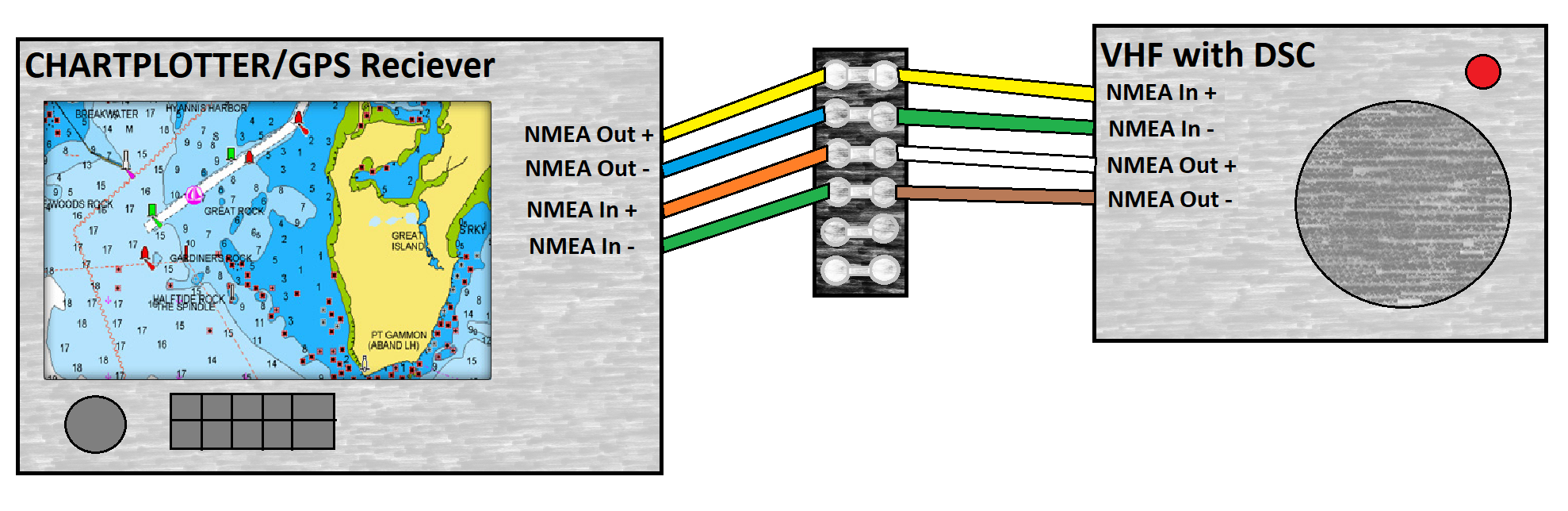 So, now we have our MMSI number and GPS data in our VHF, which means your DSC messages will now include who you are, where you are, and when the message was sent. We’re ready to start sending some messages. Every VHF will likely have a slightly different interface, so I’m not going to get into the gritty details of operations, but stay at a relatively high level overview on given operations. Distress Messages. Sending a Distress Message is probably the most important feature of DSC. While it is advisable to transmit the most detailed distress message possible, I think it’s unlikely that you’ll want to try to enter the nature of the distress, number of people on board, etc. when it’s all hitting the fan. When you’re in the thick of it, you’ll probably be happy to just send a quick message with vessel information a position. That’s pretty simple with your DSC equipped VHF, now that it’s set up: 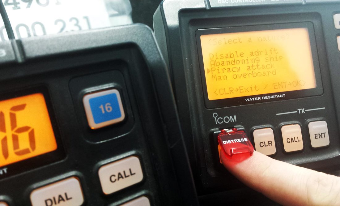
General Messages. Now we get to the fun part, sending messages to your friends. One of the drawbacks to VHF communication is that it’s a party line and you never know who might be listening in on your conversation. Let me tell you that standing watches on the bridge of a ship at anchor, I would listen excitedly to any interesting conversations. Someone would call someone else on VHF channel 16 or 13, both of which we monitored at all times, and then suggest a new channel to continue their conversation on. Without fail, I would change over to that channel as well, just to see what they were saying (note that the definition of interesting changes when you’re stuck on the bridge for 4-hours without much in the way of entertainment). This becomes problematic when you want to discuss something that you don’t necessarily want everyone listening in to, like where the prime beaching spot you just found is, or the location of your super-secret fishing hole. With DSC, you now have an option that won’t advertise your conversation to everyone that might be listening in on Channel 16. If you know the MMSI number of the station you want to communicate with, you can send a DSC message directly to them and no one else. You also have the option of creating a group of several MMSI numbers and sending messages to only that group, or sending to All Stations for a general information broadcast. These all have their uses, but I think for the average user being able to send to one station is probably the most useful feature. 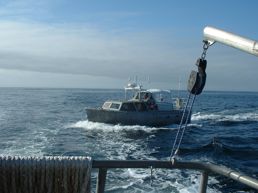 The survey launches on Rainier used to make use of this function fairly often. When 2 or 3 launches were working in close proximity to one another, they would often want to raft up together for lunch. It gave them a chance to BS with the other launch crews, trade lunch items, and generally relax. However, it wasn’t a practice they wanted to advertise to the FOO (Field Operations Officer) or CO (Commanding Officer). The FOO had two radios in his office and was always listening to the channels the launches were required to monitor, so it was tough to sneak one past him (it was me), but the more radio savvy on the crew began using DSC to clandestinely contact the other launches and arrange a meet-up for lunch.
When you initiate a DSC message, you will be able to input the MMSI number of the station you wish to reach, or select it from a stored list. You then should be prompted to enter the VHF voice channel you want to begin voice communications on, if you want to talk, but you could also enter a purely text based message (e.g. “Meet for lunch at Camp Coogan Bay?”). A station receiving a DSC call can respond via a text based message, or they can Acknowledge the call and their radio will automatically tune to the specified VHF voice channel. The sending unit will automatically shift to the specified VHF voice channel once it receives the Acknowledgement and the two stations may begin conversing over that VHF voice channel and no one else is any the wiser. If anyone is looking to give it a try, you can always send the Serenity a message; if I’m aboard I’ll be sure to reply…maybe even meet up for lunch. Our MMSI number is 338154427. Until next time, here’s wishing you fair winds and following seas.
2 Comments
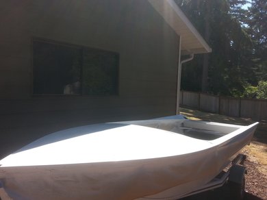
As the old C.W. McCall song goes, “I was thumbing through the want ads in the Shelby County Tribune, when a classified advertisement caught my eye. It said take immediate delivery of a ‘57 Chevrolet half ton pick-up truck…” Well, if you substitute Craig’s List for the tribune and a ’56 Lone Star Cruise Master for a ’57 Chevy, you’ve got a pretty good indication of what happened to me. About a year ago, I came across a Cruise Master while aimlessly searching Craig’s List for trouble. It was in Wichita, KS and included a 115-hp Mercury “tower of power” for the princely sum of $700. I’d never really considered buying a Cruise Master before, but after some consideration I discovered that I had to have one.  Unfortunately for me, after I had come to this conclusion, I gave the seller a call only to find that it had been sold the day before. Never the less, I now had a quest and I was on the search for a Cruise Master to take up some room in my yard, bust my knuckles on, and cuss at. I set up a search warning on eBay and for the next several months did regular searches on my favorite Craig’s List conglomerater, SearchTempest.com. I found a few possibilities, but they were either too far away or too dearly priced. Eventually my efforts paid off and I found a nice Cruise Master in Oklahoma city. After a little haggling, I was the proud new owner of a 1956 Lone Star Cruise Master with two motor mounts, one for a single engine and one for double engines, and three outboards (two matching 35-hp Johnsons and one 75-hp Evinrude). It was a prime candidate for my next project.
The previous owner had started work on her, but had moved on to other projects and needed to clear up some space. He had already removed the old transom and replaced the aluminum sheeting on the transom. He worked in aircraft maintenance and his work looked exceptional, thought he may have gone a little overboard with the rivets on the join to the new sheet.
The Cruise Master was billed as “the Queen of the Lone Star Fleet” when it was rolled out in 1954 and represented a big departure from their smaller fishing boats. Targeting buyers looking for a large weekend cruiser for relaxing on the water, it was a 21-ft long cabin cruiser that provided a lot of space and amenities. 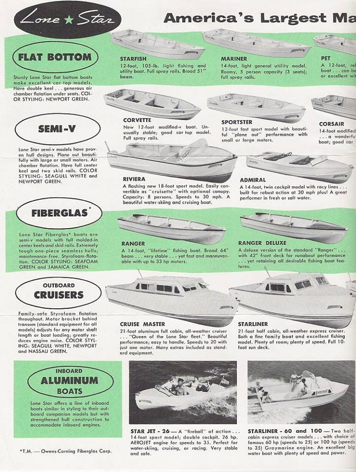 The Cruise Master remained the flagship of the Lone Star Fleet until they discontinued the model in 1961. An inboard version was offered in 1955 and ’56, but the majority of the Cruise Masters, like mine, were powered with outboards that were hung on brackets that placed them about 2-ft to the rear of the transom. They boasted standard features like built in berths, a head compartment, built in cabinets, hinged cabin windows with screens, and navigation lights. There were also several options available, including the flying bridge windshield and a head that pulls water from the lake and, as was apparently legal in the 1950s, discharges its waste right back into the lake. My new project had both of those options, but the head had been removed at some point (the stand pipes still remain).
I can picture her already in the stately “Newport Green” over “Seagull White” paint scheme with a mahogany interior and teak and holly flooring, cruising out to the San Juan Islands with my wife and son. It will hopefully be the perfect weekend cruiser to do a couple nights in some beautiful location, but it’s a long way from that point and I’ve got a lot of cussing and knuckle busting to do before then. Work on this project will be slower, since the boat is currently located in my parents back yard in Colorado. Thus far I have only managed to clear everything out and do a quick inventory. The hull appears to be reasonably sound, but someone has liberally coated several seams with silicone, which is going to be a super awesome to get off, and there is one rib in the bow that was cut through to expand storage, which I will need to beef up structurally. The hull was media blasted to bare aluminum and the bottom primed, though I think the primer is suspect and I might end up removing it; the deck and super structure still have a nice layer of flaking paint and I have purchased a sand blaster attachment for my pressure washer that I hope will make quick, easy work of getting everything down to bare aluminum and ready for paint. There are countless other projects to keep me occupied for the next year (or more), but that will all have to wait for later. Until next time, here’s wishing you fair winds and following seas. As I mentioned in the previous post, there are virtually limitless options when it comes to foam. So, what foam should you use for flotation in your boat? It can be perplexing, but hopefully after reading this you’ll have a better idea about adding flotation to your boat. 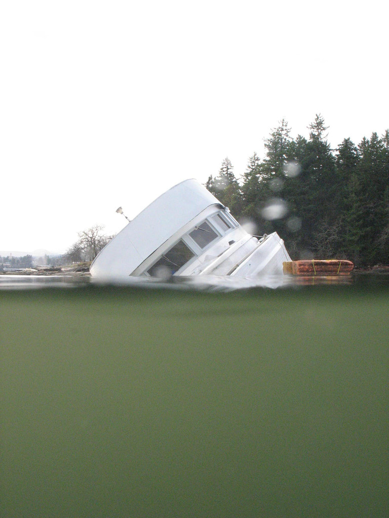 Should you even use foam at all? I’ve seen quite a few people (though definitely a minority) argue that foam floatation is just a hassle and, if you aren’t required to, you should just skip it. They argue that regardless of the foam you use, it’s going to absorb water, and it’s going to take up space. Floatation foam is designed to keep your boat at the surface with water up to the gunnels, but “they” would argue that the boat would still be a total loss having been submerged (clearly, judging from my boats, we have a different opinion of what constitutes a total loss). Obviously, I think “they” are wrong; not because the boat can be salvaged, but for safety. “They” will say they have a life jacket, so it’s no big deal, but as anyone that has done man overboard drills with a dummy knows, it’s a lot harder to spot a person floating in the water than you might think (even if their head is orange). It’s a lot easier to spot an overturned or partially submerged boat than it is to see a person. Aside from that, a partially submerged boat also provides shelter and a means to get yourself up and out of the water, which makes a substantial difference in survival time. So, the answer for me is, yes you need foam. The federal government agrees with me and per USCG requires all new boats under 20-ft to have integral floatation that will provide at upright and level floatation when fully filled with water. 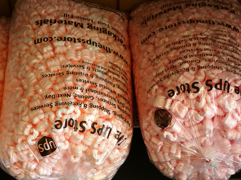 I’ve seen a few people argue for the use of sealed flotation compartments or just filling compartments with sealed bottles. They point to the fact that these flotation methods won’t get waterlogged like foam can, but the counter argument is that they aren’t as reliable as foam. Granted anything that will displace water in a large enough volume to float your boat will work for flotation. Foam provides a more resilient flotation, whereas a sealed compartment or 4 sealed milk jugs have a greater possibility of failure. Even if you damage a block of foam (break it in half, stab it with a knife, etc.), it will still provide significant buoyancy. Whereas, if you poke a hole into a sealed compartment filled with air, it will lose all its buoyancy, and poking a hole in one of the 4 milk jugs will result in losing a full 1/4 of your buoyancy. That is why I prefer foam, but I am not vehemently opposed to other methods. Now you just need to figure out what type and how much foam you need. Should you use polystyrene or polyethylene or liquid urethane foam or something else? There’s no shortage of choices and I’m not going to give you a definitive answer on which one is the best; they all have strengths and weaknesses. You need to look at their respective properties and see which one is going to fit your needs the best. The most common foams I’ve seen are the above listed polystyrene, polyethylene, or poured liquid urethane foam. Any of these should work fine, the most important thing is to use a closed-cell foam and ensure you have enough of it to float your boat and gear. Foam is made up of bubbles; in the case of closed-cell foam, those bubbles haven’t popped and thus won’t absorb moisture. Open-cell foam is like a sponge and will be useless in providing floatation for your boat. Now, to the point that any foam will eventually become waterlogged, that is largely due to improperly storing your boat or poor installation of the floatation foam in the first place. If you allow the foam to sit in water, it will eventually break down and absorb water (water is the universal solvent). In installation, you want to make sure that the foam is placed such that water can drain away from it and doesn’t become trapped (e.g. limber holes). When you store your boat, make sure the water has somewhere to go by pulling the bilge plug and raising the bow so that water will flow down and out the bilge. Even a closed cell foam has voids between the cells and will absorb some water. As an experiment I took a piece of packaging Styrofoam (polystyrene) and submerged it for a week to see how much water would be absorbed over time. The 3-in by 1.5-in by 0.5-in piece of foam initially weighed about 1.8-grams. I placed it into a tub of water and placed a water bottle on top of it to keep it submerged. The table below shows the time that the foam had been in the water and the weight at the time.
 After an initial rapid weight gain, which is a result of water making its way into the rather large voids within the foam, the weight changed more gradually as the water worked its way deeper into the smaller voids. After a week of soaking it had doubled in weight, gaining an additional 1.8-grams of water, which is about half a teaspoon. Removing it from the water and letting it dry for 24-hours returned it to the starting weight of 1.8-grams and a subsequent dunking provided similar results. So, the longer you let it sit in water, the more water will be absorbed and the more difficult it will be to fully dry out. This is more of a concern in cold climates, with freezing temperatures in the winter. Any trapped water will freeze and rupture the closed-cells of the foam. It then thaws and is absorbed into those now open-cells only to refreeze and do more damage to the foam. As this freeze thaw cycle continues the foam breaks down and will eventually become saturated with water. Keep it dry when you’re not using it (i.e. your boat sank) and it should be fine. Now, we just have to calculate how much foam you need to float your boat. The first step here is to figure out how much weight you need to float. You can do this three different ways (more really, but these are the most realistic):
Once you have this total weight, it’s a relatively simple matter to calculate the volume of foam you need to float it all. You can use the formulas from the USCG boat builder’s handbook (http://uscgboating.org/regulations/assets/builders-handbook/FLOTATION.pdf) to determine the amount of flotation needed. 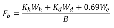 Fb is the volume of flotation needed for the boat hull, Kh and Kd are conversion factors for the materials used for hull and superstructure (0.33 for aluminum), Wh is the weight of the hull, Wd is the weight of other structural components, We is the weight of any equipment or gear, and B is the buoyancy of one cubic foot of the foam being used. Most flotation foam has its density represented as the weight of a cubic foot of the foam. Usually, flotation foam is 2-lb foam; so a cubic foot of foam would weigh just 2-lbs and displaces a cubic foot of water, which weighs about 62-lbs. Thus that foam provides 60-lbs of flotation, which is your value for B in these equations. In the Lone Star’s case, I got approximately 1.667-cuft of foam for the boat and associated gear.  Fp is the volume of flotation required for propulsion equipment and G is the weight of the engine, battery, and associated equipment. With an engine and battery weight of nearly 200-lbs on the Lone Star, I got a value of 2.5-cuft.  Fc is the flotation required for the personnel capacity and C is the maximum weight capacity. With a planned capacity of 4 people at 150-lbs each (I wish, but my wife offsets my extra cushioning), I ended up with a value of 2.5-cuft.
Once you have these values you simply add them all together to get the total required flotation requirement (in my case 6.667-cuft). In total, I actually have almost 8-cuft of foam packed in the Lone Star between the bow, the benches, and the transom. The trick really is figuring out where to put it. Now I just hope that I never need it. Until next time, here’s wishing you fair winds and following seas. When my uncle’s friend, Paul, showed up at his small private airfield in Eastern Colorado he was interested in a large box of parts on the ground in the hanger. My uncle’s cavalier response was that he had just rebuilt the upper end of the engine on his Cessna 175 and those were the left over parts he didn’t know what to do with. Paul didn’t find that particularly amusing as he was there to do my uncle’s Biannual Flight Review (BFR) and was about to go up in said aircraft. Truthfully, he had just replaced the cylinders and the box was old parts that he was discarding; he is one of the best mechanics I know and helped me and my dad rebuild my first engine (an old in-line 6-cylinder Mercury 115-HP outboard). Never the less, things always come apart a lot easier than they go back together and after finishing up the paint work I was ready to start piecing my boat shaped puzzle back together…hopefully without too many spare parts.  Prior to painting out the interior, I first tackled replacing the flotation foam. The polystyrene floatation that was concealed in the nose and the bench seats was in a sorry state with rodent nests and severe degradation from sitting out in the elements for nearly 50-years. So I cleaned it out and got to the business of replacing it. There are any number of different types of foam to choose from; polystyrene, polyethylene, polyurethane, polyisocyanurate, and polypropylene, just to name a few. Rather than going into detail on determining the right type or necessary amount to keep your vessel afloat in this post, I think I will ave that for another post. I ended up using a combination of poured polyurethane and some rigid polystyrene. The foam in the nose was held in with aluminum strips that were riveted in place; I just drilled out the rivets on one side, slid the old foam out, slid the replacement foam in and put in some new pop rivets. I wanted to remove the foam in the back bench and move it closer to the transom; given the weight of the outboard, I thought more flotation at the heaviest part of the boat would be a good idea. Also, I was hoping to use the back bench for storage. I was able to get a little over 1-cuft of foam glued under the transom well with polyurethane glue. I would have liked more, but I just couldn’t figure out a good arrangement to get more foam at the transom without major modification. I guess if it ever sinks, it's going to float down by the stern. 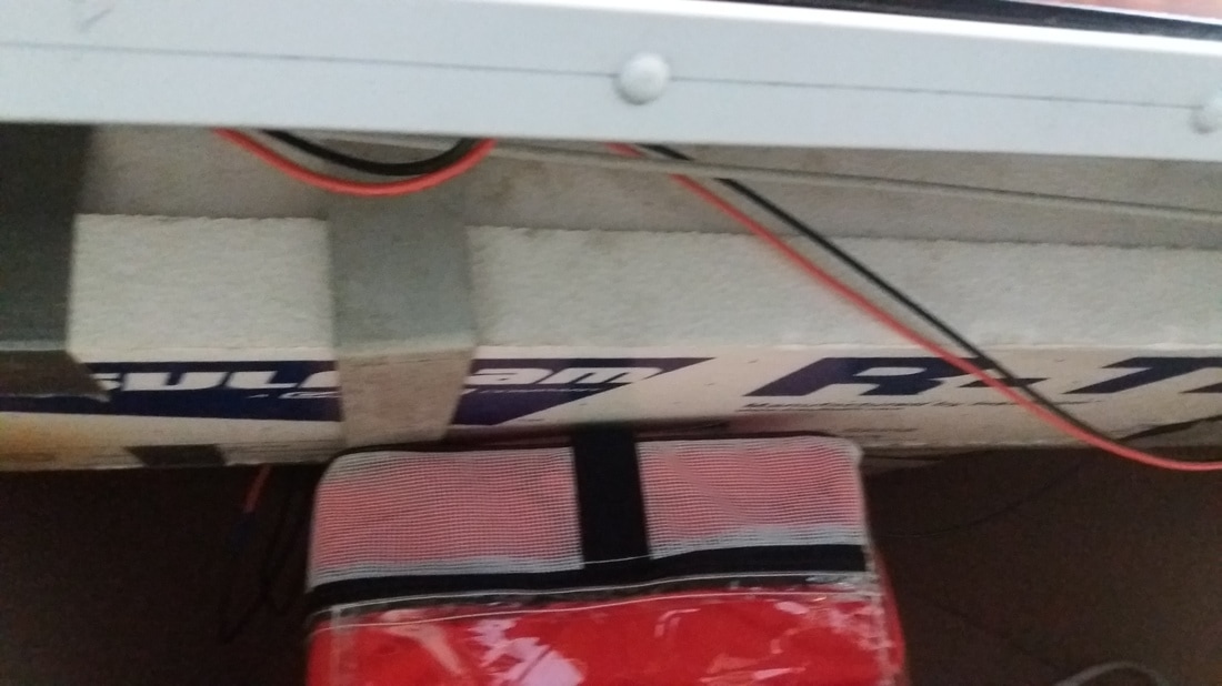 On the front bench, I decided to go with a poured liquid urethane foam. My first attempt didn’t turn out so well; I failed to read the product literature completely. The foam I have used in the past has a shelf life of 1-year prior to being opened, but the brand I purchased for this project, FGCI, only has a shelf life of 6-months and apparently they mean it. I purchased the foam about 8-months before trying to pour the bench full, since Amazon had a sale and I figured that I would use it before the end of the summer. Anyway, I poured a gallon, which should yield 4-cuft, enough to fill the front bench with a little overflow, but only got about 1-cuft of dense "foam." Luckily, I had lined the bench with plastic sheeting (disposable table cloth) to contain it and that made removal of the failed pour a snap (just pulled it out and put it in the trash). 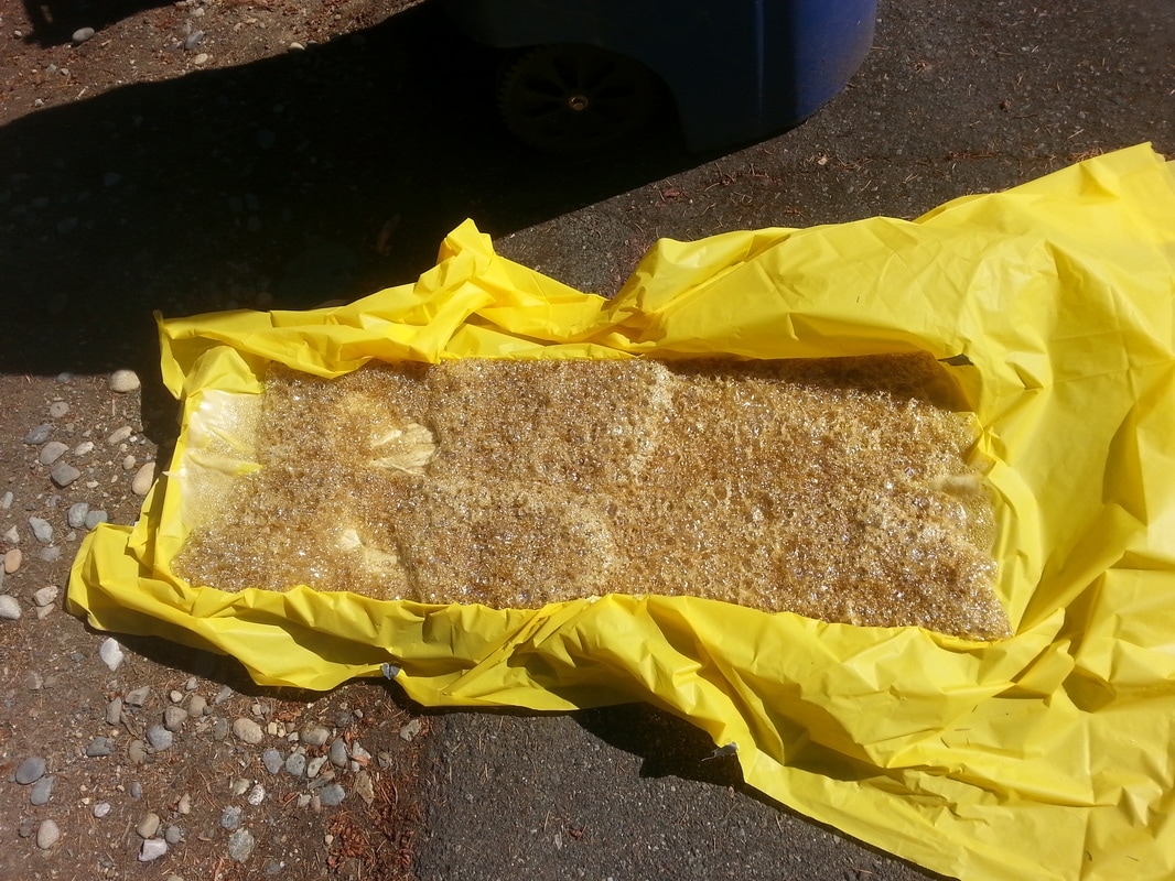 After reordering the liquid urethane foam, I made a second more successful attempt. I first laid some wood sticks in the bottom through the limber holes in the bench to keep them clear and allow water to flow to the back. I then laid in my plastic sheeting and poured the foam in two stages. The reason for breaking the pours up into two stages was firstly, to ensure I didn’t have a major overflow, and secondly, to prevent it from heating up too much. The expansion of the urethane foam is exothermic and, if you’re not careful and pour too large a quantity the excess heat will degrade the foam and yield a more dense foam than expected. When I was working at the Pacific Marine Environmental Laboratory on the TOA buoys we always poured in multiple stages. The buoys were just giant fiberglass donuts (the original mold was based off of an over inflated truck inner-tube) that were then filled with poured urethane foam. Initially they were doing this in one pour, but found that they were getting a lot of heat (so much that they worried about fire) and far denser foam than expected.
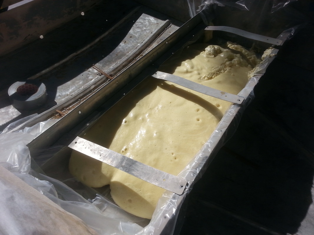 With such a small pour as this, it’s unlikely that there would have been a problem, but better safe than sorry. Even with the precautions, I may have gotten a little over zealous with the second pour, but nothing a serrated knife couldn't fix. 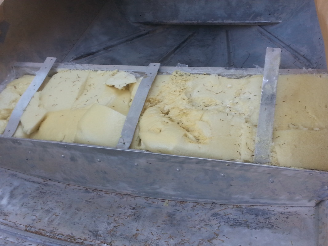 Once the floatation was in and I got the interior painted, I was able to show off my skills, or lack thereof, in carpentry. I debated adding wood to this aluminum boat; I'm not a huge fan of the maintenance that goes with bright work, but it seemed appropriate for this boat. The wood adds a lot of beauty to the boat and I don't think the dash board and bench tops will be too much of a maintenance headache; if they are, I can always remove and replace them with HDPE (high density polyethylene, commonly called Starboard) in the future. In order to make the dashboard, I created a tape template of the dash by laying up several layers of masking tape onto the dash and then just peeling it off. I then used my template to cut the 1/8-in thick mahogany plywood to size and transfer the necessary holes for switches, steering wheel, and mounting hardware. I planned to through bolt it in four spots for final mounting.
 I fabricated the seat bench tops, to which I attached standard marine folding seats, out of mahogany (both solid and ¾-in plywood). Fabrication was fairly straightforward, just measure once and cut three or four time…wait, that’s not the saying. That might have explained some of my snafus. In any case, I cut all my lumber to size and then faced the decision on how best to glue and screw them together. I was torn between doing it the easy way and having visible fasteners (i.e. screw heads) holding the bench tops together or going the extra mile and putting them together with hidden fasteners. It would be easy to clamp them and glue and screw them in place, but then the screws would be visible. Alternately, I could pull them out and fasten them together from underneath so that you can't see the screws, but keeping the geometry correct out of the boat so that they go back in without an issue would be a lot trickier. In the end I went with the easy way, but I bought brass screws and called them a nautical detail. On the plywood sections, which were the whole bench-top in front and the opening lid on the back bench, I needed to cover up the end grains of the plywood. I purchased some iron on mahogany veneer and went to work wrapping all the edges. It was pretty easy, just cut to length, iron in place, and then trim off the excess with the trim tool that I purchased along with the veneer.
Once the fabrication was done, it was time to move on to staining and varnishing. I used all Minwax products, since they are readily available from the local big box store. I seem to be fond of saying this, but I am not an expert and that is especially true of painting and finishing. Most of what I know I learned from the internet and reading the literature with the products I bought, though I do have some experience in this area that I can contribute. Staining is relatively simple. I went with Minwax Mahogany stain to give the mahogany a richer color. The staining process went something like this.
Once I had everything stained, I had to wait the prescribed dry time before moving on to varnish. In this case, the prescribed time wasn’t long enough since it was an unseasonably cold day and extremely rainy (I know, who would have expected that in the Northwest). I had to wait about double the dry time until the stain was dry, which can be tested by wiping the surface with a clean cloth and getting little to no color transfer. Once that was done, I got to move on to varnishing. Varnishing the seat tops and dash were a very slow process with all the rain and cold; as mentioned above, recommended dry times aren't so accurate when it's this cold and wet. I doubled them and still ran into soft varnish when I went to sand the first time. I used Minwax Helmsman Spar Varnish and the can recommends three coats with 4-hour dry time in between, but I went overboard and went with 5-6 coats total with a full 24-hours in between coats. My varnishing process went something like this:
I did manage to pick up a few cool tricks and tips along the way. Firstly, after mixing your varnish (never shake) it's a good idea to pass it through a filter to make sure there aren't any particulates in the mixture that will show up as flaws once you've laid down the coat; paint strainers are fairly cheap and readily available. Secondly, in order to prevent varnish from sitting in the rim of your can and sealing the lid on, you can punch a few holes in the bottom of the rim to allow the varnish to drain back into the bucket (I can't believe it took me this long in life to learn that). Third, as I mentioned above, it's better to apply your varnish with a foam roller in order to get a more even coat, which you can then tip with a good quality badger hair brush to get to lay down smooth. Forth, this is for all the skinflints out there like me, in order to reused your foam roller from coat to coat you can wrap it in a plastic bag getting all the air out you can and sealing it as well as possible.
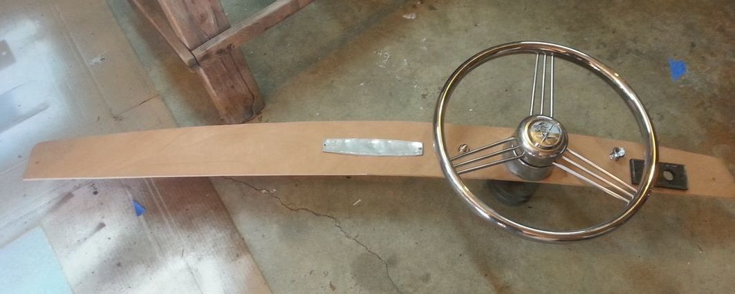
Keeping your varnished bright work looking good is not a once and done kind of thing; you will have to maintain it every year, which is why I was slightly dubious about putting it on this otherwise low maintenance boat. At the beginning of every season, starting with this one, I will have to apply another coat of varnish. That will mean removing the wood, rubbing it down with a fine grit sandpaper, and rolling and tipping it. If you don’t keep on top of this and the finish starts to go, it’s already too late and the only solution is to strip it down to bare wood and start from scratch…we’ll see how long I can keep that up. Once the varnishing was done, it was time to really start assembling the boat, which is where I really start to have fun as I see the finished project start to take shape. I made sure that all my hardware was stainless steel (except for the “decorative” brass screws I used to build the benchtops). The fold down seats were through bolted to the bench tops and then the bench tops were screwed down to mount on the bench supports. The dashboard was mounted with four screws; two dedicated mounting screws on the outside and the two mounting screws for the name plate. Regrettably, the dash nameplate was sun bleached to bare aluminum when I got it, but a contact over at the Lone Star Yahoo Group was nice enough to provide me with an image of his dash plate that was in slightly better condition. I’m looking to get the lettering reproduced as a decal, but haven’t yet found someone that can do it. I installed the switches and a 12-V power outlet, but that will be covered in another post. I then moved on to the steering wheel. 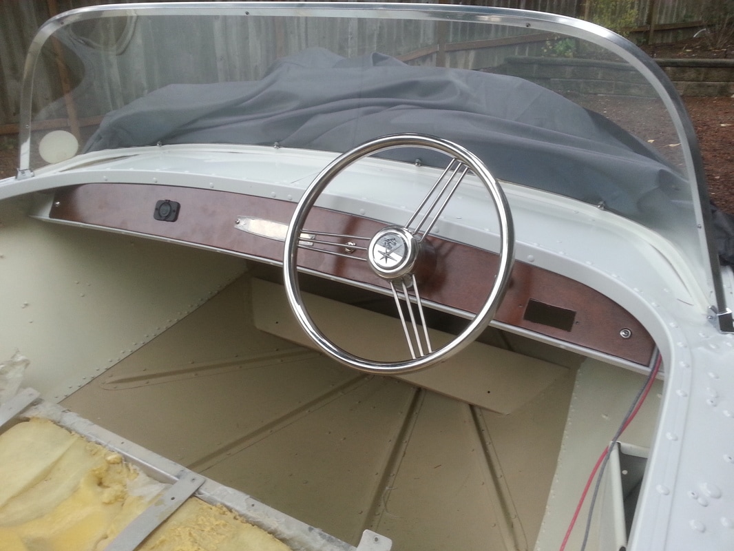 I would have liked to have used the original steering wheel and planned to restore it, but it was too far gone. I purchased a new chrome steering wheel and mounted it to the old steering shaft for the pulley steering system. I also managed to salvage the Lone Star center cover and attach it to the new wheel. I replaced the cable and re-rove it to get my steering system set up. If you’re not familiar with a cable and pulley steering system, I think it’s best described in one of my famous paint diagrams. 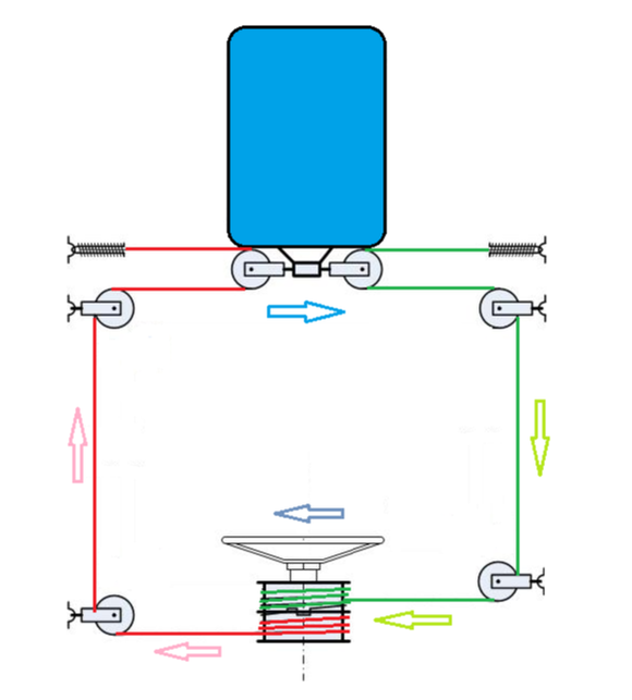
Turning the wheel to the right will rotate the drum of cable, which releases cable on the starboard side and tightens the cable on the port side. That moves the front connection point of the engine to the left, thus pushing your stern to the left and turning you to the right. I just had to mount the engine and install the control box with new control cables to have a fully operational boat. The chrome pieces were all in reasonably good condition and, aside from reworking some of the electronics, I just had to remember where they all went. My wife bought me a new old stock Taylormade acrylic windshield that fit just about perfectly. And with the addition of a few vinyl decals and the registration number, I had something that could pass for a boat.
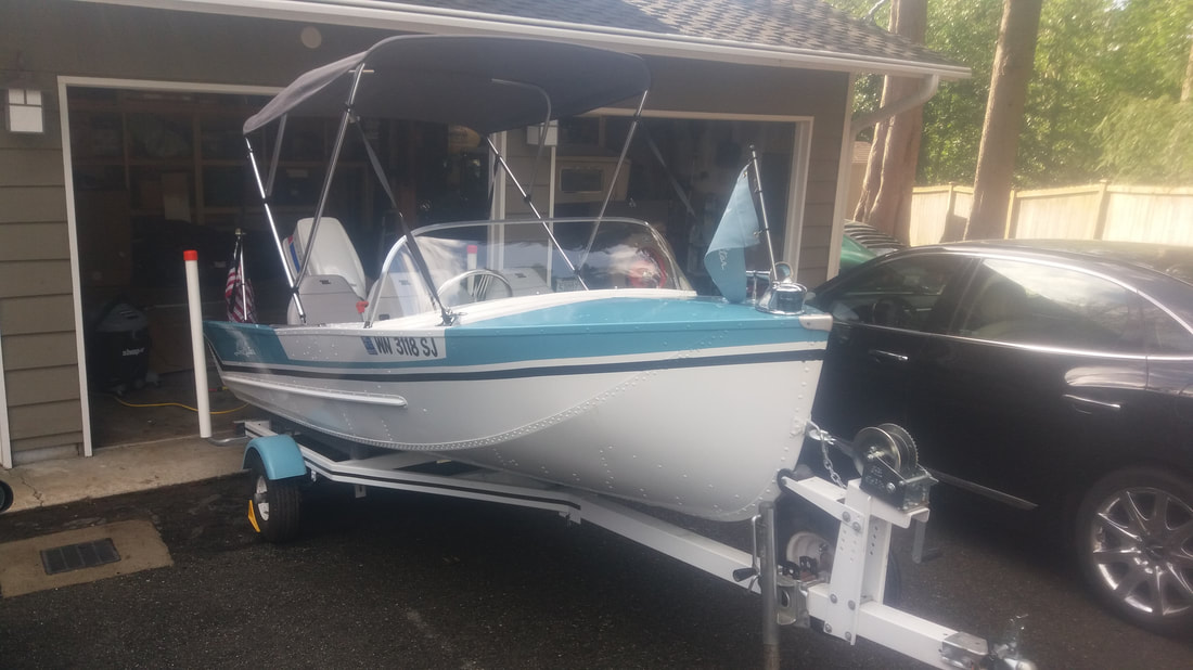  I wouldn’t call this a true restoration, but it is fairly period correct and met my desires for a cool runabout that would turn a few heads for a very reasonable amount of money. While it’s close to "finished," I've learned that as long as I have a boat, I will always have a project or two that still needs doing.
Until next time, here’s wishing you fair winds and following seas. I know a lot of you are probably reading the headline to this post and thinking…Watt? (Insert rim-shot here) I know, electricity puns aren’t very Current, but they really get me Amped up. Okay, I’ll stop, since my wife insists that my puns Hertz her. If you haven’t guessed by now, this post is going to involve electricity and more specifically the rewiring of my Lone Star Malibu. As compared to a car’s electrical system, I find that wiring a boat is really quite simple…at least a small boat like this Lone Star, a houseboat is in a whole different category (see my previous Shocking Post). Though the same principles still apply, no matter how big the job. Electrical wiring should be taken seriously, and in the world of boats, as with electrical wiring in your home, there are rules that should be followed. The American Boat and Yacht Council (ABYC) writes the standards for the wiring in boats; manufacturers follow these guidelines rigorously, but owners can tend to flagrantly disregard them. I referenced the wire sizing guidelines in my previous post linked above, and the same still holds true for this post (make sure your wire is appropriately sized for the amperage draw and the length of the run). I won’t go into chapter and verse of the ABYC standards, but if you are tackling a wiring project, they are worth consulting to make sure you are using the correct materials and following convention. I will mention that there is a wire color code that should be followed for vessel wiring set by the ABYC. However, not all boats will follow this wiring color scheme, some manufactures used different wiring schemes as late as the 1990s and you can never be sure what a previous owner might have done. If you are rewiring your boat, it would behoove you to bring it up to the current standard. 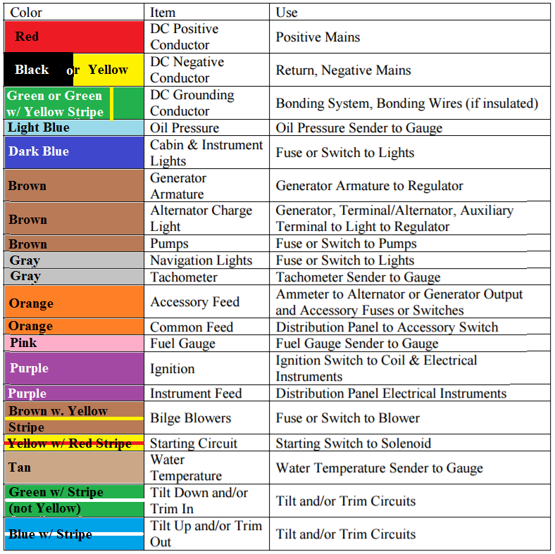 I used black for my ground and not yellow, which is quickly being phased in by manufacturers after the 1996 update by ABYC so that there was no confusion between the DC system ground and the AC system hot wires. I went with black since I had it on hand and don’t have to worry about an AC system on the Lone Star (the houseboat got the same treatment since that was the color scheme already in place). The first thing I had to do was make sure I had all my components in working order. I rewired the bow light and converted it to an LED bulb. That was fairly easy, I just pulled it apart and replaced the bulb socket with a new one that I purchased on eBay and purchased the corresponding LED bulb. I likewise refurbished a vintage stern light that I purchased on eBay with an LED bulb and a new mounting base to fit the narrow mounting surface I was left with because of the fins at the stern. 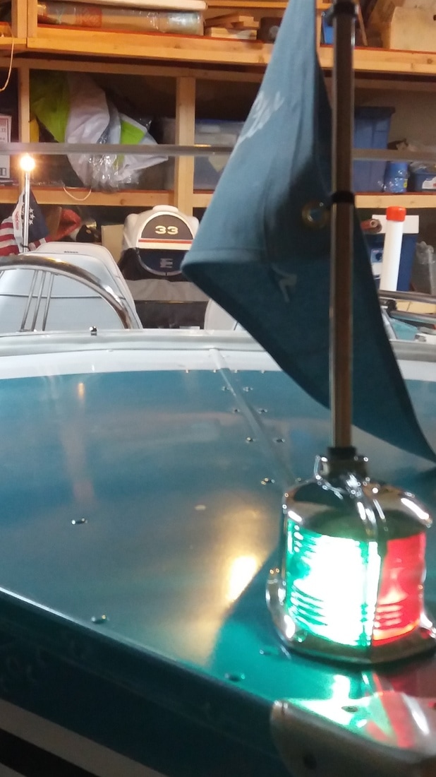 I also had to rebuild the horn, which was a slightly more involved process. I first tried to get the old horn working, but to no avail. Powering it should turn on and off a magnet very quickly to vibrate a metal diaphragm to produce sound that was amplified by the horn body. No amount of cleaning would get the mechanism working again and I was forced to look at other options. I ended up buying one of the cheap horns from Harbor Freight and pulling out the innards (diaphragm, actuator, etc.) to use in the old horn body. It wasn’t a perfect fit, so I got a 1/8-in thick piece of PVC and cut out an adapter to mount the new diaphragm on and then mount that onto the old horn body. I was thrilled when I applied power and it sounded like a horn once more.
The only other components that I had were the new 12-V power outlet that I installed on the dash and the outboard motor, which came wired with its own harness. I’d just have to connect the outboards power cables to the battery and run the supplied wiring harness to the key and choke switch up front. Now on to wiring. Normally, I’m an advocate for using a switch panel with integrated breakers, like the one pictured below. I prefer breakers to fuses, since you don’t have to worry about carrying replacement fuses, and the panel places the fuse conveniently by the switch. That can eliminate a lot of headaches with figuring out which fuse goes with which switch goes with which accessory. 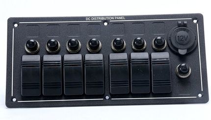 In the case of the Lone Star I wanted to have an original look and couldn’t picture a modern switch plate anywhere on the boat. As a result, I had to opt for a fuse block to run all my electronics. I suppose if I had really wanted to keep the fuses or breakers with the switches, I could have drilled corresponding holes next to the switches and installed a fuse holder or standalone breaker. I wanted a cleaner look though, so this fuse block was the best solution.
As I said, the wiring for the Lone Star was pretty simple, with just 4 components to supply. You’ll notice that I got a 6-circuit fuse block even though I’m only using 3 of them; leaving room for future expansion is always a wise decision. I don’t think I will be adding anything to this boat, but you never know. I might decide I want a radio, a fish finder, a VHF, a chart plotter, etc. There's no end to the things you can spend money on adding to your boat (a hole in the water you throw cash into), so you'll never regret leaving room for later expansion. Now, on to the wiring. I made up the below wiring diagram with the actual wire colors I used (black for ground, red for supply, gray for navigation lights, and orange for the horn and 12-V outlet), but I thought that color coding each component made it a little easier to read (bow light = purple, stern light = green, horn = blue, 12-V outlet = orange, 12-V positive supply line = red, and grounds = black ). 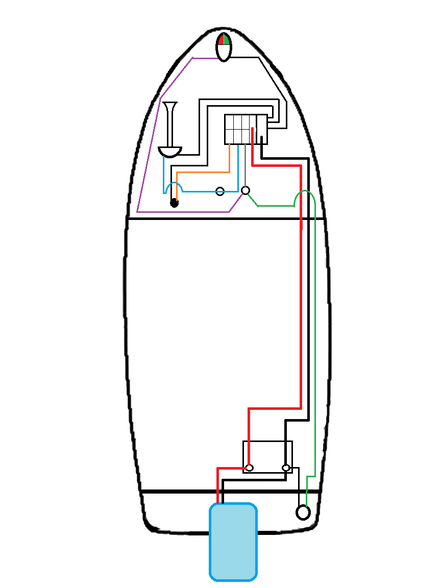 I bought myself an Optima BlueTop battery, which is an AGM (Absorbed Glass Mat) battery that is designed as a starting and deep cycle battery. It is sealed and maintenance free; it’s rated for 750 cold cranking amps (number of amps the battery can deliver at 0°F for 30 seconds while maintaining a voltage of at least 7.2 volts) and had a capacity of 55-Ah (you can draw 1-amp for 55-hours, or 55-amps for 1-hour, or something in between). I just had to give that battery a nice home. I got a battery box and mounted the strap down to a couple of ribs with the battery box sitting in between those ribs. I also mounted a battery trickle charger to that box, so that all I would have to do to give it a charge before heading out to the lake is plug it in. I also mounted a 30-amp breaker to the outside of the box and ran a 10-ga supply line through that and up to my fuse block along with a 10-ga negative line to the integral negative bus bar.
From the fuse block, I ran 12-ga wire for each of the components. The 12-V outlet was wired directly from the fuse block, fused at 20-amps. The horn was wired through a momentary push button and fused for 7.5-amps. The navigation lights were fused at 5-amps and run through a three position plunger style switch, which has one output terminal energized in the first on position and both output terminals energized in the second on position. That allows you to energize just the stern light to act as an anchor light, or energize both stern and bow lights for your standard running lights. 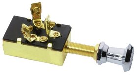 I should mention, if you’re wiring navigation lights with a rocker switch (like the switch panel I prefer above), you will need a double-pole double-throw (DPDT) switch. Run power to the input terminal of both poles, on one pole you can connect the two output terminal and run a supply line to the stern light, and on the other pole you connect only one of the output terminals to the bow lights. In my exceptional paint diagram below, terminals 3 and 4 are the input terminals, terminal 1 supplies power to the bow navigation light(s) in one of the switches on positions, and terminals 2 and 6 are jumpered and supply power to the stern light in both on positions. 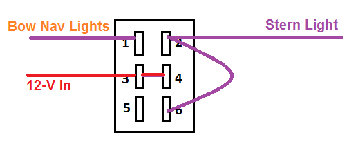 That just left the engine system, which I didn’t really have to play with too much since the wiring is internal to the outboard and the starter switch and choke were already wired into the harness. I just had to run the wires from the starter switch and choke back to the engine and plug into the harness. If you do have to work on the wiring for your engine, a shop manual with a good wiring diagram is worth its weight in gold. As I noted above, an engine this old does not follow the ABYC wiring standards and having a playbook makes things a lot simpler than having to chase wires to figure out what they do. 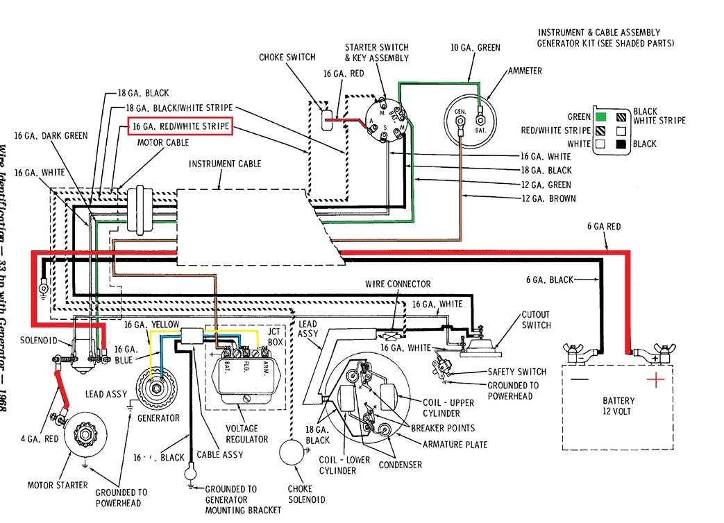 I’m thinking I may do a separate post on the outboard and marine engines in general, but for our purposes here I will detail the starter switch and choke wiring (note this will be different for newer engines). As you can hopefully see in the photo below, my starter switch and choke switch are wired as per the diagram above. The green wire supplied voltage from the engine/battery (power in); the starter switch then has four other terminals. These should be marked M, S, A, and M. I know that’s two Ms, what the heck is going on here? The S is for the starter solenoid and is a white wire on our set-up; this is powered when the key is turned to the start position (to engage the starter). The A is for accessory and is powered when the key is in the on position; if we had accessories (like a radio) that we wanted to power when the engine was on they would be run on this terminal, but in this case we only jumper from this terminal to the choke switch (red wire) which then runs back to the engine to engage the choke (red wire with white stripe). The M terminals are your kill switch; when the key is in the off position, these two terminals should be connected, which will kill your engine (black ground wire and black wire with white stripe for the kill switch). With that all connected the only thing left to do was see if the engine would fire up…but that will have to wait for another blog post. 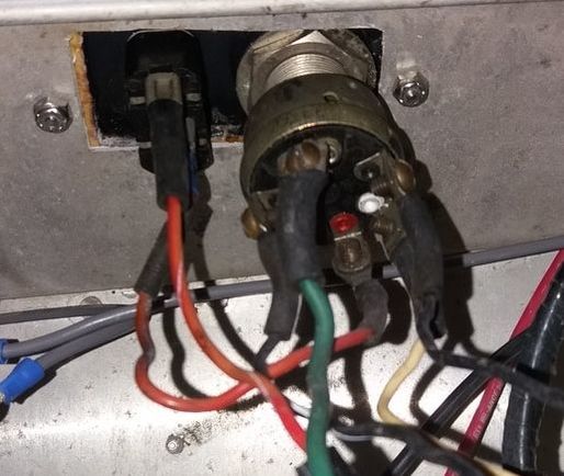 Until next time, here’s wishing you fair winds and following seas.
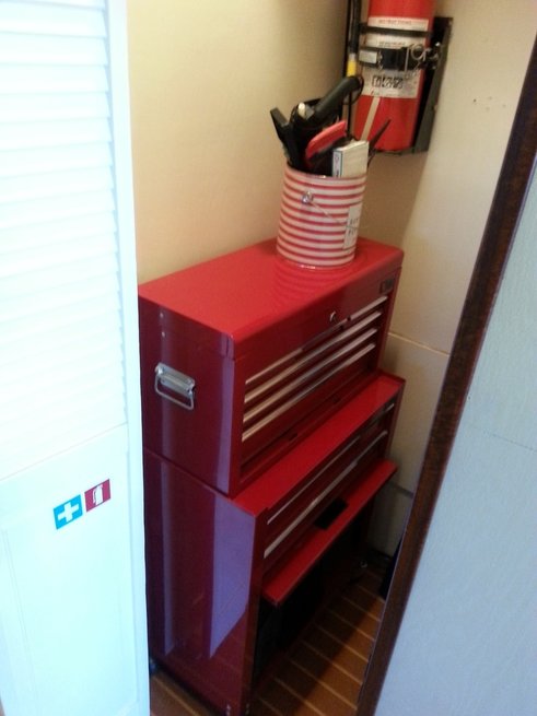
At the zoo there was a monkey island surrounded by what was essentially a moat. The island had a lighthouse on it and in the moat along the shore of the island there was a concrete sculpture of a wrecked boat, broken in half. As early as three years old, I remember thinking about how cool it would be if I could somehow put it back together and have my own kid sized boat. I guess I’ve been dreaming of having my own boat for as long as I can remember; I always saw old broken down wrecks (be it a rotted out old wooden runabout or the rusted remains of an old shrimping boat on the Florida coast) as an opportunity to rebuild them to their former glory…I hadn’t yet learned how to calculate return on investment. 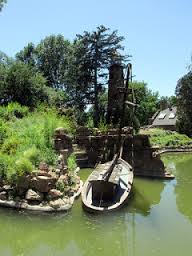 I did just that with my deck boat in high school, but after I spent some time on the water I started to dream bigger; I wanted a yacht (a 58-ft Hatteras Long Range Cruiser, in case anyone wants to get me an early Christmas present), but I could never make buying such a large vessel make financial sense. It didn’t keep me from dreaming about rebuilding my perfect boat and all the features that I would want on it. Fast forward to early 2015 when I found myself the proud new owner of Serenity and I finally had my opportunity to build the perfect boat. Granted, some features you’d want on a transatlantic yacht don’t make as much sense on a houseboat on Lake Powell (Radar, Autopilot, EPIRBS, SSB radios, AIS, ECS, Gyro-compass, etc.), but plenty do and I had other features based on my houseboating experiences on Lake Powell that I wanted to incorporate as well. I’m going to highlight all the “bells and whistles” that I added to the boat that I think separate her from other houseboats. Flooring. What, floor coverings don’t sound like a feature you’d daydream about? I think that the right floor coverings are not only aesthetically pleasing, but also offer longevity and improved livability on the houseboat. As such, I took a lot of time making sure that I chose the right ones. I’ve already sung the praises of the Lonseal teak and holly flooring in my previous post on the interior, but I’ve got to bring it up again. This vinyl flooring that emulates a teak and holly sole ticks all the boxes for me; it looks good, it’s durable, and it doesn’t require maintenance. You can easily point out that material and installation costs exceed that of carpet, but given the fact that this should have a much greater life (hopefully never needing replaced) and isn’t going to get stained or trap the sand and dirt, I think the extra cost is justified. It is a commercial grade sheet vinyl, which is a waterproof barrier, has a long wear life, and is UV stable to prevent fading. The only thing you should ever have to do to keep this floor looking great is sweep and mop, which will be of great benefit in keeping the sand that will inevitably be tracked aboard in check. 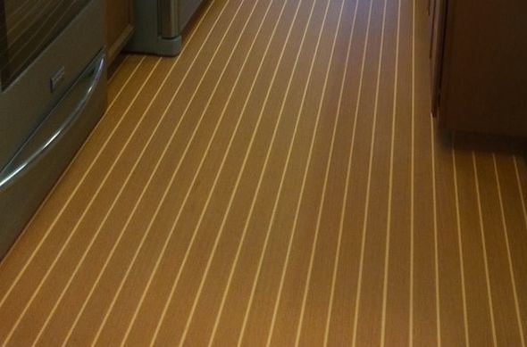 I did opt for carpet in the staterooms due to both the lower cost and the installation difficulties with the stairs. I like the feel of carpet in a bedroom, and, while I prefer hardwoods or tile throughout a house, I usually go with carpet in bedrooms as well. In order to get the best life out of the carpet, I purchased a short pile Stainmaster carpet that I hope will hold up for many years. On the exterior decks I went with a marine carpeting, but decided on a darker tan color instead of the traditional dark gray that you see on most boats. The reason for the dark tan was twofold, I figured it would be cooler on the feet and I thought that the sand that was tracked aboard would blend in with the brown tone better than a gray. Getting a quote for installation of $6000 for the front and back deck nudged me in the direction of installing the exterior carpeting myself. After a solid week worth of work, I understand why they charge so much for installation. Never the less, it came out well and I added features like the tan plastic stair caps to improve wear and longevity of the carpet (seems that the first place to wear out on carpet is always the nose of the stair treads). 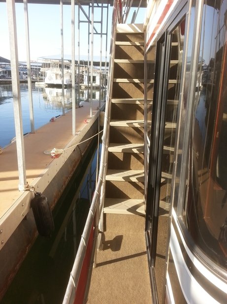 Safety Equipment. Every houseboat has the basic, required safety items; fire extinguishers, Personal Flotation Devices (PFDs), throw-able flotation, smoke and carbon monoxide alarms, etc. Of course, Serenity has a full complement of all those items, but, as someone that has gone to sea and had safety drilled into me, I went above and beyond when it came to safety equipment. I was always fond of the USCG motto of Semper Paratus, meaning always ready; it was much better than the NOAA Corps motto, which as near as I could tell was Semper Confusa (in basic training I was told that NOAA was an acronym for No Organization At All and my career seemed to reinforce that). I hope never to be caught wanting when it comes to vital equipment that might save a life; just like the boy scouts, always be prepared. The number one fear of most mariners is fire. Fire aboard a vessel is truly terrifying, especially a ship sailing in the frigid waters of Alaska; there is no fire department to call, you and your fellow crewmates are the only ones that can battle the blaze, and if you fail the only escape is the unforgiving ocean. I’ve gone through basic and advanced firefighting training twice; even with turnout gear and an SCBA (Self-Contained breathing Apparatus), getting near a raging fire was no fun. So, while I equipped the boat with 5 fire extinguishers, I was looking for better alternatives to battle a blaze. The engine compartment was already protected by a fixed HALON system, which should knock down a fire in that space in short order. It is a HALON 1301 Flooding System that is automatically actuated when temperatures in the Engine Compartment reach 175-deg F. HALON is a firefighting agent that attacks the fire by inhibiting the chemical reaction itself. It is very safe for human exposure and it is extremely effective at quickly knocking down a fire while leaving no residue. Unfortunately, it is a CFC and was linked to ozone layer depletion; as a result, production was ceased in 1994, but there are sufficient reserves to last well into the future for applications where HALON is necessary. I'm very happy to have it protecting Serenity's engine compartment. 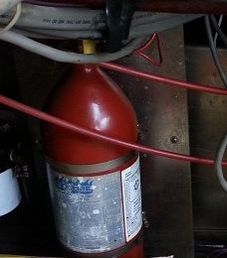 At the suggestion of my firefighter brother, I installed an automatic fire suppression system over the range called the “StoveTop FireStop,” which is a fixed Sodium Bicarbonate Dumping System. This system is automatically actuated when flames reach the device and ignite a fuse. The fuse triggers canisters of Sodium Bicarbonate, which are dumped onto the range to extinguish the fire by smothering; when sodium bicarbonate is heated it releases carbon dioxide gas, which deprives the fire of oxygen. My brother also pointed me in the direction of a new sort of extinguisher, the Elide Fire Ball. The Serenity is now equipped with 2 Elide Fire Balls, which act as fixed automatic fire suppression systems in the main salon above the electrical panel and in the aft stateroom. These Fire Balls can also be taken down and thrown into a space to combat a fire without having to make entry or attack the fire directly. They are a hollow polystyrene ball containing monoammonium phosphate dry chemical surrounding a small explosive charge. Flames will ignite a fuse, which will set off the explosive charge and distribute the firefighting agent evenly throughout the space. 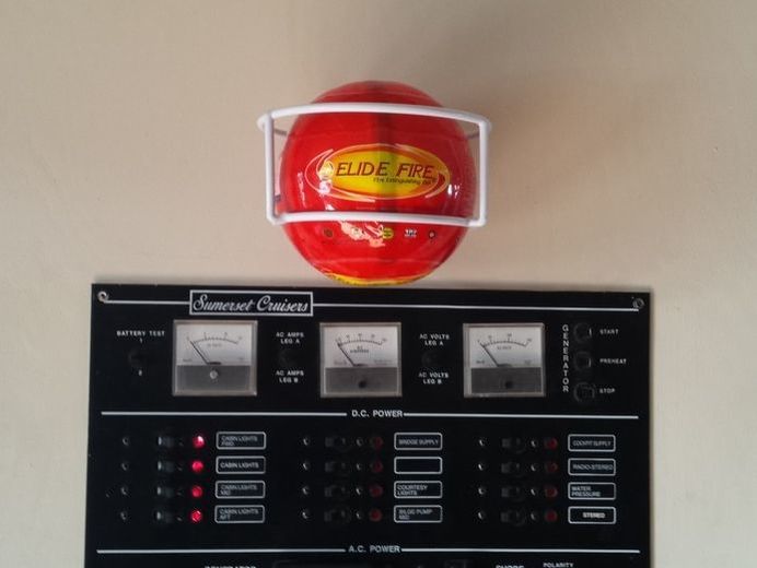 Medical emergencies, like fire, pose a unique hazard in a location as remote as Lake Powell. Minor and major medical problems can arise at any time and having someone on board with at least basic first aid and CPR knowledge could be the difference between life and death. I went through over a month of training (most of which I have forgotten; I don’t think anyone wants me giving them stitches or administering an IV) to receive my MPIC (Medical Person In Charge) certification and I wanted to be sure that I had all the required emergency medical equipment available if I would ever need it. The Serenity is equipped with a very extensive Medical Kit that will provide equipment for even advanced responders; from a Cervical Collar to stethoscope to SAM splints to Aspirin. I had to restrain myself from buying a back board and AED, but at some point I had to admit that the expenditure exceeded the likelihood of ever using the equipment. Either way, someone that is trained in emergency medicine should find everything they need for basic EMT level care in the utility closet. All the emergency equipment in the world isn’t worth a tinker’s dam if you don’t know how to use it and haven’t thought about how to react in an emergency. On board ships we had binders of Standard Operating Procedures and Emergency Procedures that we had to learn inside and out to get qualified as bridge watch standers. Similarly, I have taken great care in creating SOPs and Emergency Procedures for the Serenity. They detail the equipment aboard and how to use it with clear and concise explanations. This sort of information is invaluable and, likely to the consternation of some of the new owners, it is required reading prior to being authorized use of the boat. As part of our rules, the owner also has to conduct a safety briefing prior to departing the slip, to make sure that everyone aboard knows the key safety elements aboard the boat. Safety is everyone’s responsibility. 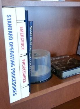 Navigation Equipment. I’m a self-admitted navigation nerd, having spent countless hours on the bridge of a ship navigating through the inside passage to and back from Alaska, and I had to reign myself in so that I didn’t overdo the navigation equipment on Serenity. Realistically, there is very little navigation wise that you need on Lake Powell other than local knowledge, but there are a few things that can definitely make your life easier. I of course purchased a suite of charts for the Serenity, including the Fish-n-Map charts of the north and south lake, the Stan Jones map that I framed on the wall for quick reference, and Navionics Western Lake electronic chart package, which includes a very detailed electronic chart of Lake Powell. The electronic charts display well on the new Lowrance Elite 7 chart plotter and echosounder (that’s the hydrographer’s way of saying depth finder), which also gives you a wealth of information about water depth and temperature. I mounted the chart plotter at the upper helm, since that is where I would be driving once in open water, where the chart plotter would be most useful. While I would never want to navigate the lake at night (it’s specifically prohibited by our insurance), this would give me far more confidence in doing so. 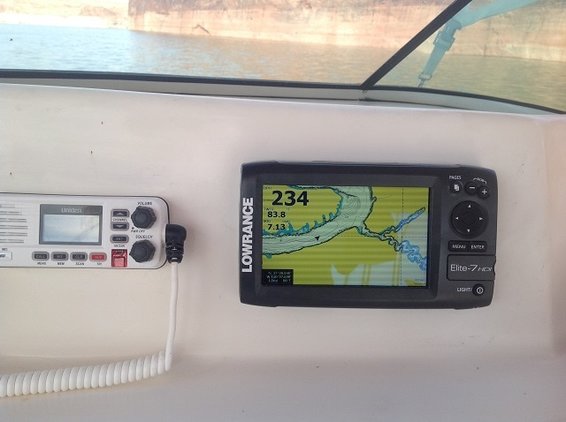 Navigating in open water is relatively easy, but maneuvering in tight quarters can be a nerve rattling experience. As such, I focused on adding anything that could make the process a little easier. I had to replace the rudder angle indicators, which are extremely helpful in close quarters. It’s a nightmare trying to maneuver that houseboat in tight spaces when you have to guess at where your engines are pointed. After pulling into the slip for the first time, I realized that the view behind the houseboat from the lower helm was limited, to say the least. Having someone on the back deck as a lookout works, but I thought it would be much easier if you could see for yourself. I installed a rear view camera to give the driver a clear view of what is behind the boat. We’ll also be installing rear view mirrors on both sides soon to increase visibility further. 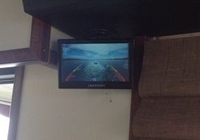 Luxuries. Now, if I had my way I’d have a much simpler houseboat, maybe an aluminum pontoon boat about 50-ft or less in length with a swamp cooler and camper appliances; something that would be inexpensive to operate and be a little bare bones. When I think about going to Lake Powell I don’t think about creature comforts, but I’m married now and apparently if I want my wife to come with me to the lake, I need a few luxuries. I also figured that some memorable features would make shares easier to sell. I went higher end on most things, like soft close doors and drawers on the cabinets and stainless steel appliances, but also added a few cool extras.
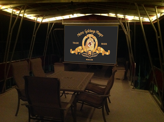
 As I’ve said, the work on a boat is never finished, but this post pretty much wraps up the ongoing series on the refit of the Serenity. I’m sure I will have many projects on the Serenity to write about in the future (winterizing the boat, the installation of the water slide, replacing the canvas, etc.), so stay tuned.
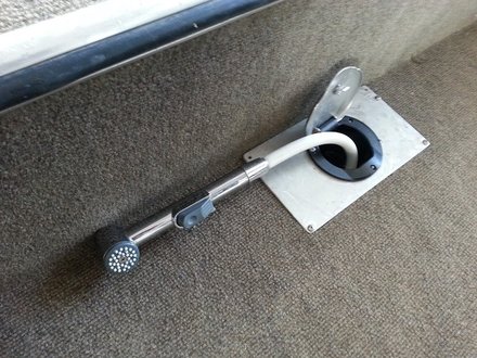
Until next time, here’s wishing you fair winds and following seas. When I was sailing on the NOAA Ship Rainier, we had no shortage of open houses and tours for everyone from Congressional staffers to local kindergarten classes. Giving tours of the ship, I got sick of drawing the analogy that the ship was “like a small floating city and was completely self-sufficient; producing its own power and fresh water, and treating its own sewage.” Never the less, it’s true and is equally true, though on a smaller scale, on a houseboat like Serenity. I’ve already address the electrical systems, so, as you may have guessed, this post is going to detail the plumbing systems.  While the ship had water makers that turned sea water into fresh through evaporation and had a full MSD (Marine Sanitation Device) system that treated our waste water for discharge into the ocean, houseboats usually have far simpler systems. Generally you will find tanks on either end; potable water tanks to carry your fresh water supply and black-/gray-water holding tanks to carry waste until it can be pumped out. There are some houseboats that have water makers (usually reverse osmosis), but a majority are like Serenity and just have potable water tanks for your drinking water supply. The Serenity is somewhat unique in her fresh water configuration; supposedly the original owner liked to take long, fresh water showers and ordered it from Sumerset with five 80-gallon fresh water tanks, for a total of 400-gallons of potable water. The tanks are interconnected to act as one tank; connected via the fill lines and vent lines at the top and the supply lines to the pump at the bottom. With so much potable water, they made the unusual decision to not have a lake water system. Every other houseboat that I have experience with has a separate system run to the sinks and shower that is supplied by drawing water directly from the lake. That way you can use the lake water for all your non-potable applications and conserve the potable water. Aside from the fact that you are pumping your water from these tanks, the houseboat’s water supply lines are virtually identical to those you would find in a home…or more precisely, a mobile home. 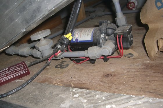 All the piping on the houseboat was gray polybutylene (PB), which was widely used in stick built homes, but was even more common in the mobile home industry. For anyone that knows plumbing, they’re probably cringing right now. PB was the precursor to the PEX lines that are commonly seen today, but was plagued with installation problems, connector failures, material degradation, and other issues leading to catastrophic failure. It was manufactured from the 1970s through the mid-90s, but was phased out amid lawsuits regarding homes damaged by water leaks and the rewriting of plumbing codes to eliminate its use. There are any number of problems, particularly with early installations. Issues mainly had to do with the fittings (the acetyl plastic and aluminum crimp fittings were the most common source of failure), but also due to micro-fractures in the pipes that resulted from excessive UV exposure or chemicals in the water. Many would have gone the route of completely re-piping, but unlike a house, I think that replacing the pipes as needed is more reasonable. Luckily, the fittings on Serenity were all compression fittings, which did not display the same issues found in the crimp fittings and have proven reliable. The PB piping itself has also held up very well and shows no sign of deterioration (inside or outside the pipe). In a house, if a PB pipe failed, you would likely be looking at tens of thousands of dollars of damage; you might not be home when the leak occurred and thousands of gallons of water could be unleashed into your home, damaging drywall, dropping ceilings, and doing other major damage. Unlike a house, the houseboat’s water system should only be pressurized when someone is aboard, so a catastrophic failure should be noticed, and the water would drain relatively harmlessly into the bilge, where it could be pumped out without causing nearly as much damage as in a house. If the pipes were in good condition, I left them as they were. However, anywhere that I needed to do plumbing work, I swapped them out for PEX lines, using the specialized crimp adapter to convert from PB to PEX. As future work is done, I expect all the PB pipes will be swapped out to PEX eventually. We will just need to monitor the system to make sure it doesn’t have any issues. The system itself is fairly simple. As illustrated below, there is a fill point on the starboard side of the houseboat, which will pressurize the potable water system or will fill the five potable water tanks if you open the valve inside the hatch just aft of the helm station. Once the tanks are filled, you can pressurize the potable water system with the pump, which needed replaced with all the other electronic components. In pervious boats and my parent’s campers I was accustomed to the buzzing rattle of the pump, but to my pleasant surprise, the pump I put on Serenity (a SHURflo 12-V, 3-GPM, 55-psi self-priming diaphragm pump) is virtually silent. From the salon, directly over where the pump is mounted, you hear nothing when it is running and you get a consistent, steady stream of water from any of the taps. 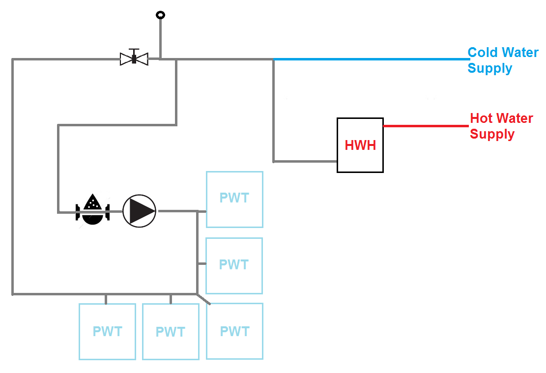 When utilizing the on board water supply, the water is pumped through a UV filtration system before it ends up at the faucet. The UV filtration system, “The Water Fixer,” was installed prior to my taking ownership of the boat, but I did get the fun of completely rebuilding it. I purchased new filter housings, new ballast and electronics, new bulb, new quartz tube, and rebuilt the stainless steel housing for the UV tube. There is a two stage particulate filtration (standard mesh filter and charcoal filter) before the water passes through the UV chamber, where any living microorganisms that managed to make it through the filters should meet their fate. The water aboard Serenity should taste as fresh as if it had come from a mountain spring. 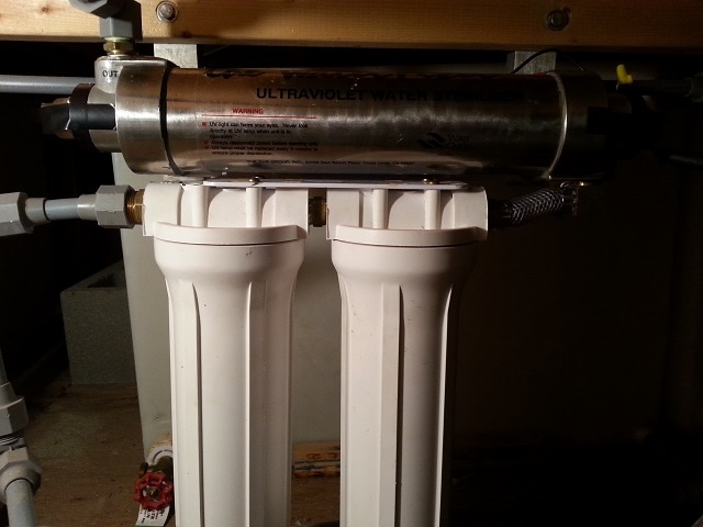 From the filter, the water goes to the individual fixtures as the cold water supply and also runs to the hot-water heater. The water heater, of course, needed to be replaced; I went with a 10-gallon Reliance 120-V hot-water heater that was a pretty straight forward swap out. Then the hot water is run to the individual fixtures, just like in a house. As shown in the above diagram. As far as waste water, Serenity is old enough that she was built with no gray water tanks and instead discharges gray water from the sinks and shower directly overboard. Other than plumbing in the new sink drains, the gray-water discharge didn’t need any work. The drain from the shower and sinks just run via standard PVC drain pipes to a stand pipe towards the stern and is discharged overboard. Serenity does have three 80-galon holding tanks for black-water from the two marine heads. It is a mystery to me, with all the room in this hull to position the holding tanks, why they didn’t do drop heads. Drop heads are far cheaper and simpler with less likelihood of failure, but instead they have two marine heads. The heads are Raritan Atlantes 12-V macerating heads, which I got to rebuild (no end to the fun of fixing up this houseboat). I contacted Raritan Engineering and got all the replacement parts to upgrade them to the current models (A8), which basically replaced all the internal components on the porcelain bowls.  Each head has an electrical switch attached to the flush handle; that switch actuates either the macerator pump that removes water and other…waste…from the bowl and pumps it to the holding tanks, or the supply pump that feeds water into the bowl. While I did say earlier that the Serenity did not have a lake water system, I suppose that statement isn’t strictly true as both heads have dedicate supply pumps that draw lake water from seacocks. These are the only points, aside from engine cooling water, where Serenity pulls lake water aboard. I’m glad that I didn’t have to deal with multiple lake water systems, mainly due to my concern with the Quagga mussels that have recently been moving into the north end of Lake Powell. However, this still leaves me to worry about the potential damage they might do the black-water system and I have spent far too much time researching potential solutions. I haven’t found anything definitive on whether these mussels will cause problems in the black-water system, but it stands to reason that since they are a concern in waste water treatment plants that you might see similar issues in your houseboat’s black-water system. I considered several different options for preventing this theoretical damage and have found that there is a dearth of information on actual implications of these invasive mussels on boat systems and on appropriate and effective countermeasures.  Chlorine and other chemical sterilization is proven to kill the mussel veligers. However, like most houseboats, Serenity is using an enzyme based toilet treatment and chlorine would kill off those desirable enzymes. Additionally, adding chemicals to the toilet to kill off the veligers wouldn’t really protect the pump or supply lines. If chemically killing the critters wasn’t an option, then I thought the next logical method would be to irradiate them. Serenity already has the UV filtration set up on the potable water, and I didn’t think it would be too difficult to add a UV sterilization chamber onto each of the supply lines, which would have no impact on flow rate. UV Sterilizers use short wavelength UV light to kill microorganisms on a genetic level; damaging their DNA so that they cannot perform basic, vital cellular functions. I just wasn’t sure that this would be completely effective on the mussel veligers. I only found one study on the efficacy of UV light at killing Quagga mussel veligers (note the link to the study now just redirects to the home page of the Aquatic Invasive Species Network, it appears they have taken down the study). This report looked at the effectiveness of single and multiple treatments though a UV sterilizer at killing Quagga mussel veligers. I didn’t think the conclusions were well supported by the data (they advocated multiple treatments with the UV sterilizer, even though after 96-hours 1-treatment has greater than 90% mortality rate, which was statistically the same as the multiple treatment runs) and I would have liked to have seen more definitive testing (they only looked at the mobility of the veligers in the sample up to 96-hours after treatment to determine mortality; I would have liked to have placed the samples into an ideal growth environment to see if any of the UV treated veliger samples would produce mussels) and a larger sample size (if I recall correctly, they only ran one sample for each treatment level). I briefly toyed with the idea of getting some water with veligers from Lake Powell and conducting my own experiments, but decided that 1) that would be a lot of work and 2) I’m pretty sure that knowingly transporting an invasive species across stateliness is probably against the law. I didn’t have my definitive answer, but I thought that it looked good and was about to start calling UV sterilizer manufacturers. Before I got to that, I posed the question on the Wayne’s Words Message board, figuring that I couldn’t have been the first person to deal with this issue. No one had considered this for combating potential mussel infestation, but UV sterilizers and filtration systems weren’t a foreign concept (mostly on potable water systems). One member had an issue with sediment getting picked up into his black-water system and had success with a standard canister filter system on the lake pick-ups. I had dismissed a traditional filter because I was worried about providing sufficient flow rate to the heads, which require at least 3-GPM, but he said he was using 5-micron filters in his system and had no such issues. In fact, he only changed the filter once a year. It may not be as high tech as irradiating the little buggers with UV light, but it should be completely effective (a 5-micron filter isn’t going to let any of the 70-micron or larger veligers through) and it was much cheaper. I decided to go ahead with installing high flow rate filtration systems. 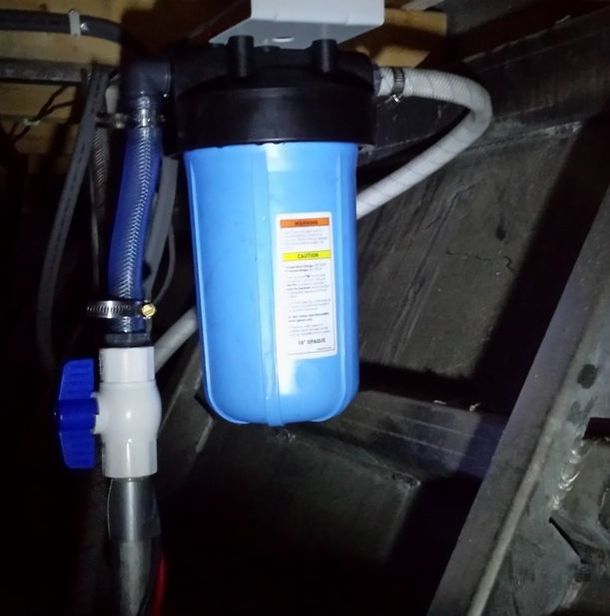 I purchase two 10-in filter canisters with 5-micron filters (rated at 5-GPM), which should have no issues removing the veligers. I’m hopeful that we will see similar results and not need to change the filters until the beginning of next year. Thus far, it seems to be working great with plenty of flow rate to both heads. It gives me one less thing to worry about; now I just wish there were a way to protect the engine cooling systems.
Until next time, here’s wishing you fair winds and following seas. In this post, I will be taking you through the odyssey that was painting the hull on the Lone Star. It was a long and sometimes arduous journey, but the end result turned out pretty well for a novice painter. In case that introduction didn’t make it obvious, I am not a professional painter and I don’t even play one on TV. This was my first foray into a project this size and I made a few tactical errors, but with some help from the internet and just following product guidelines, it was more than doable. Still I would say this isn’t really a “how to” as much as it is a “how I should have” guide. As a friend of mine, who is a professional painter, is fond of saying, “Always be sure to read, understand, and follow the instructions with all the materials that you work with.” As long as you do that, you should have a pretty good luck. I started off with a test project of sorts and repainted the cowling to the 1968 33-HP Evinrude Ski-twin that I bought off Craigslist. The engine ran well and everything seems to be in order, but a previous owner had decided to customize it by painting it out white and sticking some Boston Whaler stickers onto it. I was looking for something a little more stock and so I stripped it down to bare fiberglass with Citristrip, which surprisingly only took one application to strip off at least three layers of paint. I then primed it with one layer of self-etching primer, one coat of bonding primer, and then three coats of gloss white. After the paint fully cured, I was able to apply the replacement Evinrude stickers that I bought off eBay. I repainted the front cover plates that had flaked off with flat blue (after self-etching priming), and hand painted the blue and red "E" on the back of the engine with acrylic paint. It turned out well, so I felt confident enough to move on to the bigger project.
To begin with, I needed to remove the old paint from the hull. I mentioned in the trailer post about testing how solid your old painted surface was with a piece of duct tape, but in the case of the hull it was obvious that the paint had failed (it was sunbaked and peeling off all on its own) and the boat needed to be stripped down to bare metal. So I removed all the various chrome bits that were still attached to the boat and set to work. There are a few options available to you to remove your old paint, but being that I was doing this on a tight budget, having it professionally done by either media blasting or dipping wasn't really an option. So that left me with two basic options; mechanical removal (sand paper and wire wheels) or better living through chemistry (chemical paint stripper). I had trouble deciding which would be more fun, so I did both. Primarily, I planned to use aircraft stripper, which is truly nasty stuff. With its extremely caustic nature, I figured it would make quick work of the already peeling paint work. The claimed 10-minute strip time was a little optimistic, I found that it needed to set for at least 20-minutes before you could start peeling paint, but it worked fairly well at removing the two layers of paint that were on the boat. However, after doing most of the boat I decided to try another more environmentally friendly stripper called Citristrip and was very impressed with its performance. It seemed to be easily as effective at removing the paint from the boat and had far less odor. As with any caustic chemicals it’s important to utilize proper PPE (personal protective equipment), so I geared up with a chemical respirator, elbow length rubber gloves, and eye protection…I still managed to get some stripper on my upper arm while leaning over the boat and had a mad dash to the sink to rinse it off. Luckily, I was working outside, so a well ventilated area wasn’t a problem; I just had to contend with the alternating 90-degree days and cold rainy standard Seattle weather. It was a fairly straight forward process. Just pour on some of the stripper and spread it out evenly using a chip brush, then come back over it with a plastic scraper and stiff bristled brush to remove the toxic goo that resulted. Using a plastic scraper is advisable since aluminum is a very soft metal and going at it with too much vigor with a steel scraper can result in nasty gouges. Once I had made the pass with the stripper and my scraper I decided I needed to resort to brute force to finish the process. There were lots of crevices and areas around rivets that I just couldn’t get at with the scraper and that didn’t come clean, so I attacked those with a wire wheel on my drill. Be sure to use a stainless steel wire wheel, otherwise you might find that bits of the ferrous wire get embedded in the aluminum and can cause rust in the future. After that I ended up going over the entire hull with a palm sander and heavy grit paper to get all the last remnants of paint off and get a good key on the surface. 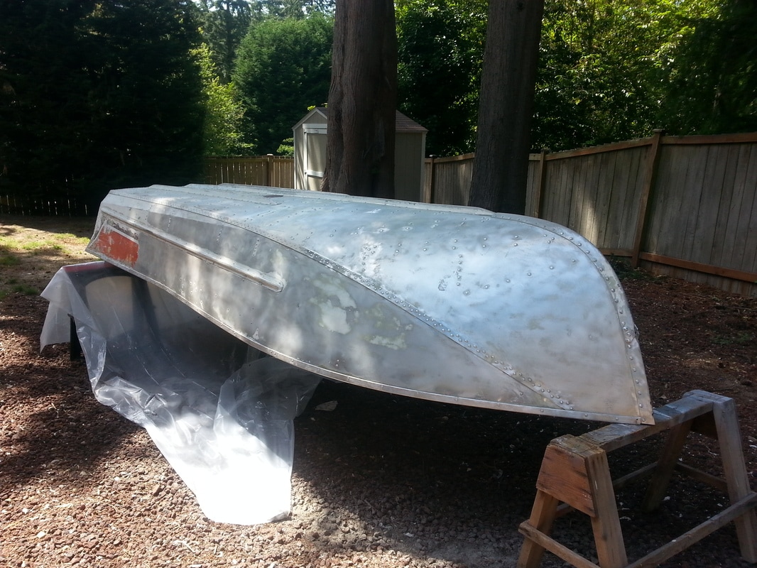 After weeks of work, I finally got the boat stripped down to bare aluminum. I did this all in two stages, working first on the top cap/deck and then flipping the boat over onto sawhorses to do the lower hull. Luckily, these aluminum runabouts are incredibly light and I was able to get it off the trailer and on the sawhorses by myself. I was pleasantly surprised to find that the hull was very straight with only one or two minor dings
At some point, a previous owner decided to drill holes in the side of the boat and mount rusty steel eye bolts (to be fair they probably weren’t rusty when he installed them) to tie down a boat cover. I had removed the eye-bolts, but prior to beginning the painting process I needed to deal with those holes. I purchased some all-aluminum closed end pop rivets (don’t use the rivets with the steel shank, as the remaining portion of the shank will rust) and coated them liberally with 5200 marine sealant/adhesive before inserting them and popping them into place. I also patched up the redundant upper bow eye holes with an epoxy putty, that I treated much like bondo and formed and sanded to blend seamlessly into the hull. 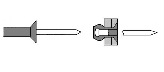
With that I was ready to break out the spray cans and get to making it look pretty again. Now, here is where I would have diverged from my plan if I had to do it over again. Assuming that like me you were trying to save money and not going to pay a professional to paint the boat, you have essentially three options. You could buy a spray gun and get some paint mixed up, you could buy some paint and roll and tip it, or you could buy an indeterminate number of spray paint cans. Those are listed in order of preference, best to worst options…of course I picked the spray paint cans. Can’t change it now, so nothing but to move on. Any method you choose will require some specialized preparation and treatment for aluminum. The first concern is making sure your primer and paint will stick to the surface; to do this, you must etch the surface. You can get self-etching primer and I used a specialized Aluminum Primer that did not require etching, but I decided to go the extra mile and etch the hull before applying it anyway (better safe than sorry). To do this, you simply mix up a 50/50 ratio of white vinegar (a mild acid) and water, apply it with a spray bottle and maintain a wet surface, spraying as needed, until the surface gets slightly darker and dull. Once that is done, wash it off with soapy water and dry thoroughly prior to applying your first coat of aluminum primer. 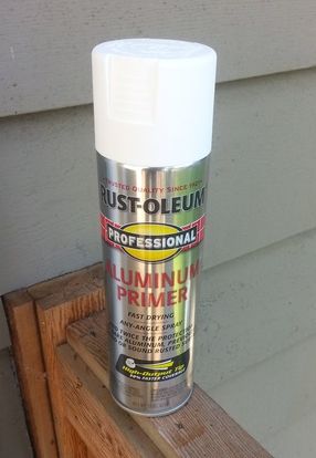 I did one good coat of Rust-Oleum Aluminum Primer and then followed that with two coats of Rust-Oleum bonding primer. Then did four coats of Rust-Oleum Gloss White Enamel. This is where reading and understanding the directions is very important; make sure you know the appropriate dry times and recoat times for the paint you are using, otherwise you’re going to run into problems. I want to be clear that I’m not shilling for Rust-Oleum (although I would if they wanted floated me an endorsement deal); however, it is a good idea to utilize one paint system from base coat to top coat, as it is less likely that you will run into issues with the paints interacting unfavorably. In my case, the Rust-Oleum enamel was dry in 2-4 hours, but does not fully cure until 24-hours. However, don't confuse these with the recoat times, which state that you may apply an additional coat within 1-hour of the previous coat or must wait 48-hours to recoat. I opted to apply subsequent coats within 1-hour of finishing the previous coat. If you apply another coat in the window between 1-hour and 48-hours after you last coat, the paint is still off-gassing and it will result in an alligator-skin or wrinkling appearance. Your only choice then is to wait for it to dry, sand it down, and then wait the 48-hour dry time again before recoating. These times are different for different brands of paint, just be sure that you read the label and know when your recoating window is. I worked in four phases; masking off the top deck to paint just the lower hull when it was upside down on the sawhorses, masking it off to paint just the top deck after flipping it back over onto the trailer, masking off and painting the graphics, and painting the interior. The hull and the top deck were both coated in gloss white. Once I finished the lower hull, I let it cure for a full week prior to flipping it back onto the trailer and working on the top cap. Then I moved on to the graphics.
 I had taken detailed pictures prior to stripping the hull with measurements and reference points, so that I could recreate them. I decided to go with a teal instead of the original red (at least I keep calling it teal, but my wife insists on referring to it as “Tiffany Blue”…I think she might be hinting at something, I’m just not sure what?).
Here is where I ran into a few problems. Remember that wrinkled finish, well turns out that not only refers to additional coats of paint, but also masking over your yet un-cured paint. I’m impatient and I masked off the teal graphics before the 48-hours was up; I didn’t paint until after the required time had passed. Alas, the damage was done, with the paint under and around the tape wrinkling up. It was frustrating, but there was nothing for it except to sand it down, back mask the teak and repaint. There are still traces of the wrinkled paint and various other minor imperfections; hopefully I will be the only one that notices them though.
With the outside looking sharp, it was time to tackle the interior. I’m going to do a separate blog post on the total interior rebuild, but the painting went pretty much the same as the exterior. Strip, etch, aluminum primer, bonding primer, and top coat. I went with a light tan on the sides and a darker tan Rust-Oleum spray on bed-liner on the bottom. The Rust-Oleum bed-liner I used is best equated to just a thick paint and doesn’t have the texture that one would normally associate with a truck bed-liner. It did however, provide a nice grippy surface and will hopefully be a durable coating that holds up well under hard use. Prior to painting the interior, I did have to make sure that it was water tight. I leak tested the boat before I started working on it. I simply put a plug in it and filled it well above the waterline. After a few hours no major leaks were evident, just a slight drip from the seam between the transom and the bottom of the boat. Never the less, I played it safe a sealed all the seams with Gluvit, which is a two part waterproofing epoxy. Application is simple, just add the catalyst to the tin of epoxy and then spread on with a chip brush. The consistency is about that of honey and it has a long work time so that it can flow into all the cracks, crevices, and pin-holes. It dries flexible and is supposed to move with the aluminum, which of course can flex. I applied it from the inside only on the transom seam with a good heavy coat, but did both the inside and outside of the side seams in lighter coats. As with most epoxies, it is not UV stable and must be over coated with something, like paint and bed-liner, necessitating mechanical abrasion to ensure adhesion of the over coat.
For a paint job that was done by a complete novice, outside under a pine tree that seemingly never stopped shedding needles, I think it turned out pretty well.
Until next time, here’s wishing you fair winds and following seas.  One note of caution before I begin, in case you don’t remember the song from Louie the Lighting Bug, electricity is dangerous. While the 12-V DC system most likely won’t electrocute you (12-V isn’t high enough to overcome the relatively high contact resistance of the human body…I feel a tangent coming on and I haven’t even started the post yet) it can pose a variety of other dangers (high current can arc and cause fires or burns, and under the right circumstances lead acid batteries can explode). The 120-V/240-V AC system is a very real threat of electrocution (potentially fatal) and also has the risk of being the source of a fire. So, if you’re not comfortable working on your electrical systems, don’t; but you can still enjoy reading about them. I don’t know how I was so deluded that I let my dad convince me that the electronics on Serenity would be fine, but somehow I had this vision of just getting new batteries and having everything fire right up and work like a charm. I mean, nothing was powered when it went under water, it was only under for a couple days, and then it dried out in one of the most arid places in the world; sticking your cell phone in a bag of rice works, and what is the Great Basin Desert, if not a giant bag of rice. Well my giant houseboat shaped cell phone did not come back to life after drying out. As a rule, every piece of electronic equipment that was underwater needed to be replaced.
Now, I could go on and list every component that was replaced, but that doesn’t make for a very exciting blog…unless you like lists. Suffice to say that we did end up replacing everything; from the outlets and switches on the 120-V system to the 12-V gauges and switches on the lower helm. There were a couple notable exceptions. The chest freezer on the front deck kicked on and froze my ice packs in a hurry; I kept it and assumed that when it did fail it would only be a couple hundred dollars to replace. The bilge blower worked, but had a new feature in a horrible squalling noise that let you know when it was on; you’d never forget to turn it off, but I eventually decided to replace it with a slightly quieter model. That’s it, literally every other electronic component was replaced with new. 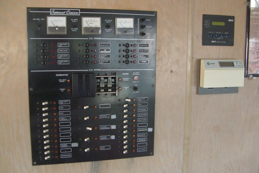 Instead of just listing the trials and tribulations of installing new electronics, I was thinking I would discuss the electrical systems aboard the houseboat in a more general way. Many people approach electrical work with trepidation and view the electrical systems on their houseboats as almost mystical in nature. I’m not going to advocate that a novice take on rewiring their home (see warning above), but I would say that a basic working knowledge of how your electrical systems work and confidence enough to troubleshoot minor problems might be a good place to start; ideally your electrical problem solving will extend beyond cycling the power (that’s a more technical way of saying "turning it off and on again"), though in some cases that does the trick. I had a lot of experience working with “system integration” on NOAA’s survey launches (getting the half million dollar sonar to talk with the quarter million dollar DGPS/Inertial navigation unit). I was up to my eyeballs in wiring diagrams, baud rates, NMEA strings, power requirements, and the like; most of which I have completely forgotten, but the experience was invaluable in tackling this project on the houseboat and keeping things in perspective and organized. 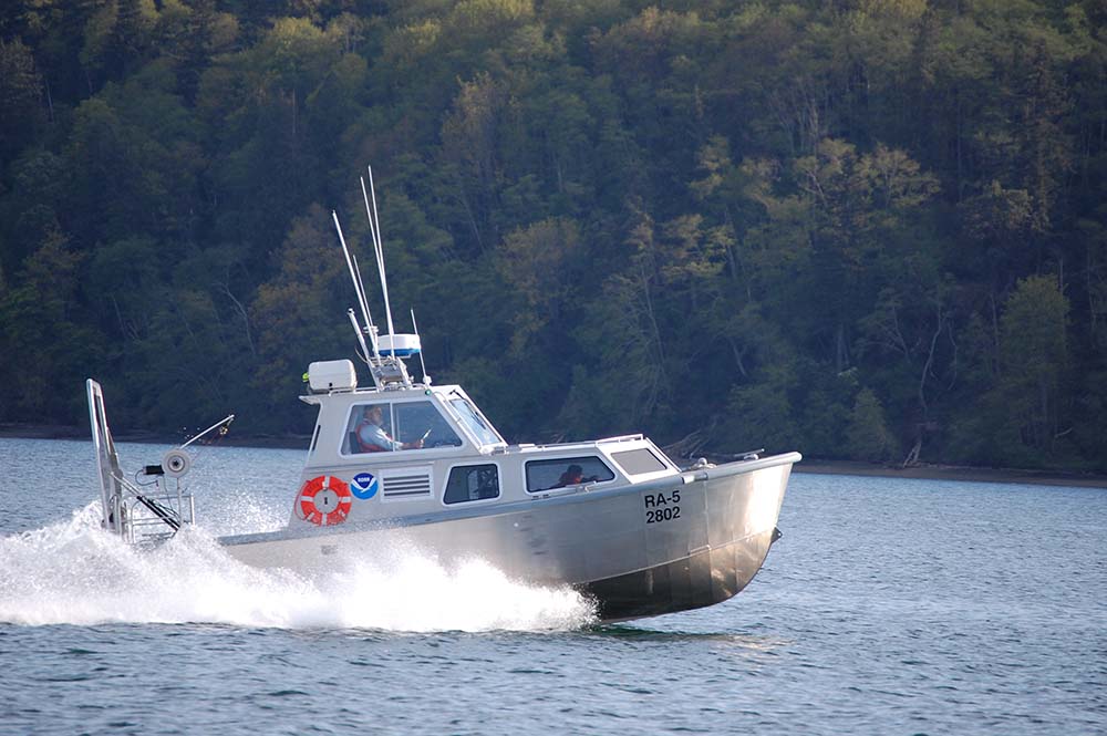 I’ll break the Serenity’s electrical system down into 3 sub-systems; the DC house system, the AC house system, and the engine system. Each of those sub-systems could then be broken down further into more sub-systems, and so on until you got to individual components. Looking at it this way makes what could be a complex and overwhelming project (i.e. rebuilding the entire electrical system) seem far more manageable. You just have to tackle one sub-system at a time until you get the whole working. The three main sub-systems were easily separated and were, for the most part, standalone systems and would function completely independently from one another. The first one that I wanted to get working was the 12-V engine systems, which are the critical systems to run the boat that can be seen as analogous to the systems you have in your car. These are common to a 14-ft runabout or a 65-ft houseboat. The navigation lights, the instrument clusters, the bilge blower, the engine’s electrical controls, etc. Unfortunately, I wasn’t able to address most of these components until the new engines were installed and the wiring harnesses were in place, which seemed to keep getting put off. So, I ended up finishing up the other two systems first. The DC house system, often referred to as the 12-V system, is relatively simple, especially if you break it down to its basic components. I think most of us probably learned about electricity in elementary school by connecting the positive and negative sides of a battery to the appropriate terminals on a light bulb, maybe even throwing in a switch, which demonstrates a basic DC electrical circuit. That is all that the 12-V system is on the boat, a DC circuit that just has a few more parts. You have a bank of 12-V batteries (in our case two sealed lead acid deep cycle 200-Ah batteries) that feed a distribution panel (i.e. the breaker panel) and then power any 12-V components. Primarily on the Serenity, these were the 12-V lights, but also include radios, water pumps, and a few other 12-V components. The two batteries are wired in parallel (i.e. negatives-to-negative and positive to positive) so that they supply 12-V, but output Amperage is doubled. The positive lead is then protected by a circuit breaker (in our case a 100-A breaker). I will note that this could be fused protection, but I prefer to use breakers whenever possible. If you trip a breaker, say by accidentally shorting the positive and negative connections on a 50-A breaker (not that I have ever done this), then it’s only a matter of resetting the breaker; if you blow a fuse, you will quickly discover that nowhere within 50-miles of Bullfrog has a 100-A replacement fuse and the only way to restore power is to bypass the fuse protection or improvise your own “fuse” (say a piece of 12-ga wire). From the 100-A breaker our supply line ran to three 50-A breakers in the engine compartment, which in turn fed the two marine heads (each head was on its own 50-A breaker) and the main DC breaker panel. Power is then run through appropriately sized breakers on the panel to feed those circuits. At each step away from the batteries, we move to a smaller breaker (e.g. 100-A to 50-A to 10-A or 20-A at the panel) and smaller wire size. You just need to be sure that your wire is appropriately sized for the amperage and the length of the run, which can quickly be determined by consulting the chart below (courtesy of Blue Sea Systems, which has a great article on selecting appropriate wire size here). Then you just need to make sure you have breaker (or fuse) protection for that run of wire. The supply line is connected, often through a switch, to your component (light, pump, radio, etc.) and the negative is connected back to the battery, often through a bus bar, to complete the circuit. 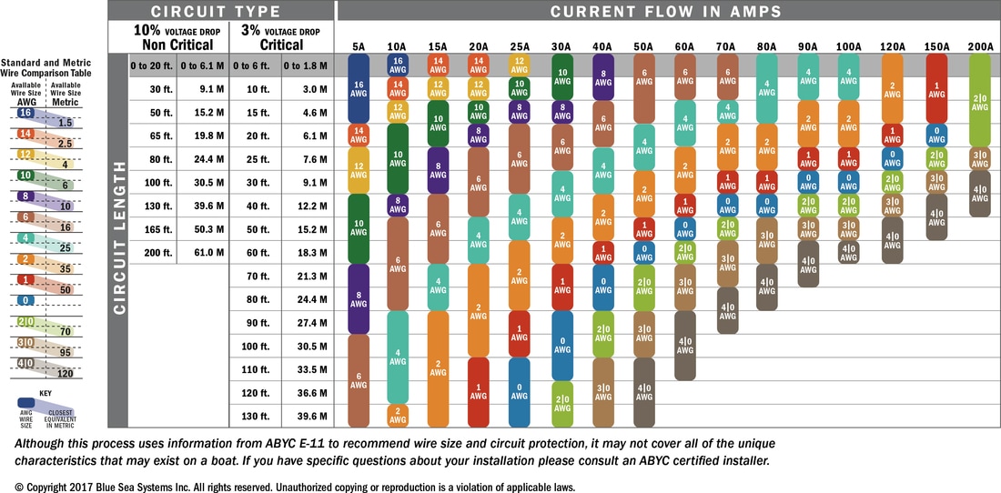 The house DC system is pretty simple, but it was not without its gremlins. The biggest hurdle we had to overcome was an intermittent problem that I initially thought was a dead short on one of the circuits. We spent an entire day trying to isolate the problem, but intermittent problems are the toughest to diagnose. The system was working without an issue right up until we had our marine survey; during his inspection he couldn’t get any of the DC components to operate. We could energize the entire DC panel without issue, but when we would put a load on the system the voltage would intermittently drop to zero. The reason is obvious now, but I was ready to bribe a friend that was an electrician to come down and figure it out for me. As anyone who has struggled with trailer wiring probably knows, the first thing you check is always the ground, which is where I should have started in this case. One of the ground wires in the engine compartment was loose and, I'm guessing, the marine surveyor disturbed it when he was crawling around and it resulted in an intermittent connection problem. Tightening the cable solved the problem. With that done and the engines still not installed, I moved on to the AC system. I will often refer to this as the 110-V system, though that is not really accurate. On the houseboat, as in your home, we have a two phase AC system, with two legs of 120-V alternating current that are 180-degrees out of phase with each other. The power at your receptacles should be 120-V, but due to resistance in the system that voltage can often drop to 115- or even 110-V. Many appliances will be rated at 110-V, which only indicates that they can safely operate at these reduced voltages, but they are actually made to run on the 120-V circuit. So, at least in this blog post, I will be referring to them as 120-V and 240-V, but know that if you see references to 110/220 or 115/230 they are referring to the same AC power supply. I don’t want to get too mired in theory (maybe I do), but it’s important to understand that your AC power is being delivered on two 120-V legs and that you can feed 120-V circuits by drawing from one leg to neutral or you can feed 240-V circuits (ranges, microwaves, HVAC systems, etc.) by using both legs. 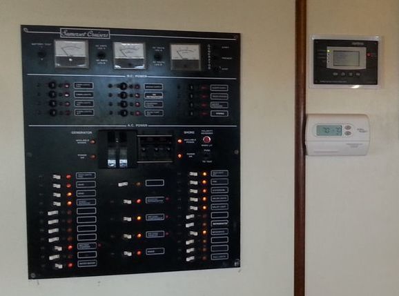 Aside from the above, the AC system is wired much the same as the DC system, running from the main distribution system (i.e. breaker panel) to all the individual circuits, just like your home electrical system. On the panel of Serenity you have three banks of breakers; the two outer columns are 120-V breakers and the center column are all the 240-V breakers. The obvious difference between your average house and the houseboat is that the houseboat has three options for the power supply. The entire panel can be run by either connecting to shore power (e.g. the power grid) or the onboard 12.5-KW genset; or, a subset of specific systems can be run by the inverter. The inverter and its dedicated bank of six 6-V 370-Ah batteries, of course, needed to be replaced. The batteries are in a separate compartment at the bow of the boat and are wired in series to create a 12-V bank (i.e. two 6-V are wired in series to provide 12-V and then each set is wired together in parallel to triple the amperage rating). The inverter is set up to provide power to the refrigerator and the entertainment center, as well as a few other minor items on those circuits. It is also supplied through the power panel to act as a 150-A charger when there is shore or generator power to recharge the batteries. I have a control panel for the inverter mounted by the main electrical panel, but it operates automatically in most situations. If the breaker is on and there is power available, it will automatically go into a charging cycle and, when the batteries are fully charge, will then shift to a maintenance charge. When power is lost, it will automatically shift to inverting after a few minutes. The one thing that has been necessary to fiddle with on the control panel is adjusting the charge rate, especially if you want to operate another heavy load like the range, microwave, or HVAC systems. I found 70% seems to work pretty well, but haven’t tried operating another big load and the 150-A charger at the same time on generator yet; it might mean lowering that charge rate even more so as not to put too much load on the generator. 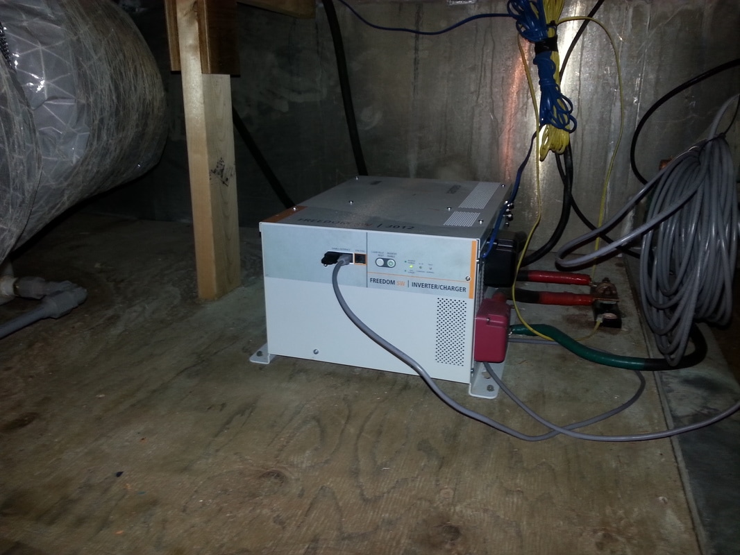 Finally, we come to the engine electrical systems…but, just like me, I think you’re going to have to wait. As I said above, these systems are largely the same from a 14-ft runabout to a 65-ft houseboat and I think I would do them more justice by devoting a full blog post to them in my series on the refit of my Lone Star Malibu.
Until next time, here’s wishing you fair winds and following seas. They say it’s what’s on the inside that counts and, in the Serenity’s case, she was as ugly on the inside as she was outside. So we ripped out her guts and replaced them with new shiny guts. If nothing else, you will get a lesson in nautical terminology and will get an idea of what my first few weeks on a ship were like; “it’s not a door, it’s a hatchway FNG….there are no stairs on a ship, Butter Bars, they’re called ladder-ways…it’s a head, if you want to use the toilet, swim to shore.” Ah, good times. As you can see from the previous photos, the interior of Serenity needed some serious help. It was a time-warp back to the mid-90s with its pickled oak, brass fixtures, and white appliances. Oh yeah, and it was underwater for a few days and seemed a little worse for the wear. I really was shocked by how much water damage there was and how much was not salvageable. The finish on cabinets and walls was peeling, plywood paneling was delaminating and bowing, cabinets were literally coming apart at the seams, the doors were falling apart, and everything was coated in an oily, sandy grime. It wasn’t a place that you wanted to spend a lot of time. And did I mention the style was straight out of the mid-90s. By the time we were done about the only thing that remained original were the overheads (that’s the ceiling for you lubberly types, on a ship a ceiling is something you stand on and the thing over your head is, well, an overhead). First came demolition. We hauled off the water damaged furniture, broke out probably 500-pounds of granite tile countertops, demoed the cabinets, pulled up carpeting, took out the doors, removed damaged paneling, and got rid of the appliances. Then we made our first tactical error; I had been thinking of keeping the tile in the galley (that’s kitchen), but my dad noted that they had installed it around the cabinets and that our new cabinets wouldn’t fit the holes. He also pointed out that the tile didn’t really fit the planned new décor, which I agreed with and agreed to tearing it out. About three days later we realized that someone was really good at laying tile; they had set down 1/8-in cement backer board with mastic, screwing it down every 6-in or so, and then put a generous amount of thinset down to lay the ceramic tile. We had broken up all the tile with roto-hammers, but the backer board did not want to let go and we finally came to the realization that the only way we were going to get the floor out was to tear out and replace the plywood subfloor. It took another couple days to clean up the edges enough to use our circular saw to cut out that section and pry it up.
We then replaced the flooring with exterior grade plywood, which was rather straight forward…except for actually selecting the plywood for use. It is an interior area and for the most part is fastened to wood structure, but there are several aluminum deck beams that the decking material would be in contact with; why is this a problem you ask? Believe it or not, the internet is on fire with debate about what wood products to use on aluminum boats, but I have yet to find any authoritative sources on the subject. Without wading into the discussion too far myself, I think what I can take away from my hours of research is: (1) I should find a new hobby. (2) You should avoid using pressure treated lumber in contact with aluminum, because of the potential for increased corrosion in the aluminum due to the chemicals in the pressure treated lumber (I could elaborate, but...). (3) For areas that will not see excessive amounts of moisture, you can safely substitute exterior grade plywood for marine grade plywood; the chief difference is that that marine grade plywood should have no voids in the interior laminate layers to prevent trapped moisture from causing rot and it may have more layers. Since this floor was interior, it was more than reasonable to just go with the exterior grade plywood. With the easy part over, it was now time to put this mess back together. We started out with repairing and replacing damaged paneling; luckily we only found slight surface mold on some of the panels, with some significant bowing and peeling of the veneer. There were happily no signs of mold behind the panels that we removed and we gave everything a nice wash-down with Lysol. Once the paneling and subfloors were done, we sanded everything down and were able to quickly move on to painting. The original paneling was a pickled oak that was popular in the early 90s, but seemed a little dated. I decided to go for a more classical yacht motif and paint the bulkheads (that’s walls) an antique white with plans for mahogany or teak (at least something that resembled one of those woods) trim throughout. The paint went on smoothly; the trim on the other hand turned into I can't count how many days of endless fiddling with angles and lengths and trimming them…I really hate finish carpentry. While I started out with delusions of saving the old cabinets, it didn’t take long on our first trip back down there to realize that they were completely water logged and well beyond saving. The finish was peeling, most of the doors were warped, and a lot of the frames were starting to come apart. I went with solid wood cabinets with boxes made out of plywood instead of particle board. They might be slightly more expensive in the initial purchase price, but they are far more durable and will hold up in a marine environment much better in the long run. I also opted for the soft close doors and drawers. We hung the cabinets and installed new laminate countertops; I used laminate countertops for two reasons, (1) the extra weight of a solid surface countertop would have kept me up at night, and (2) there wasn’t a fabricator that I could find that would go down to Bullfrog to install a solid surface countertop. Also, I should point out that I would normally wait to install cabinets until after the flooring was down, but in this case, with our time limited down in Bullfrog, I didn’t want it to hold up progress; we had contracted out the flooring and, as I discovered with everything I contracted out, things take a lot longer to get done down at Lake Powell. Long before I purchased this houseboat I had fallen in love with this vinyl flooring produced by Lonseal that mimics the look of teak and holly sole. I love the look of teak and holly and nothing is more nautical than a cabin sole covered from stem to stern in teak and holly. I was not as in love with the price, the installation, or the upkeep of traditional teak and holly flooring. Luckily, several years ago they started producing exterior synthetic teak flooring (PlasTeak, NuTeak, and a variety of others) and a little more recently there were companies that began producing the vinyl sheet flooring that reproduced the look of teak and holly with all the benefits of a commercial vinyl floor. The Lonseal isn’t cheap by any means (the 300-sqft I purchased was around $2500 and the adhesive added a couple hundred), but it is durable commercial grade vinyl. The vinyl surface is designed for high traffic commercial area, completely waterproof, slip resistant, and UV stable; in short it should outlast the boat. Without taking a long hard look at it, you also wouldn’t easily be able to pick it out from a real teak and holly flooring. I opted to lay this vinyl flooring in the main salon (living room), galley (kitchen), and passageway (hallway, though that one should be obvious); not only does it look great, it also won’t trap sand that will inevitably be tracked aboard and cleans up easily with a broom and mop. The heads (that’s restrooms) were tiled in a Stain-master “Luxury” vinyl tile, which went down over a latex primer on the plywood deck. I did contemplate installing real tile, but there is something that is just un-seamanlike about putting extra weight on a boat; I figured if the vinyl tile doesn’t hold up I can always replace it in the future. The staterooms (that’s bedrooms) were finished off with Stain-master carpeting. I contracted out the Lonseal and carpet installation, but tackled the heads on my own.
The old hollow core doors were in sorry shape and clearly needed to be replaced. I purchased traditional mahogany hollow core doors, stained and varnished them and then replaced the door hardware before hanging. The fixtures throughout went brass; I know many will think that dated, but brass was and is common on vessels for its superior performance in a marine environment…I can recall many an anchor watches as a new ensign spent polishing all the brass work on the bridge. Brass just fits with a traditional yacht décor. The exception would be the galley where I went with a stainless steel sink, stainless steel appliances, stainless steel faucet, and oil rubbed bronze (black) door and drawer pulls for the cabinets throughout. The last thing we had to do was to take a steam cleaner to the overhead to clean up some staining; then we just had to move in new furniture to complete my vision of a traditional yacht interior…if only doing it was as easy as writing about it.
Until next time, here’s wishing you fair winds and following seas.
|
AuthorBrent Pounds has over a decade of experience in the maritime industry and has been involved in recreations boating since he was a child. See the About section for more detailed information. Archives
October 2016
Categories
All
|
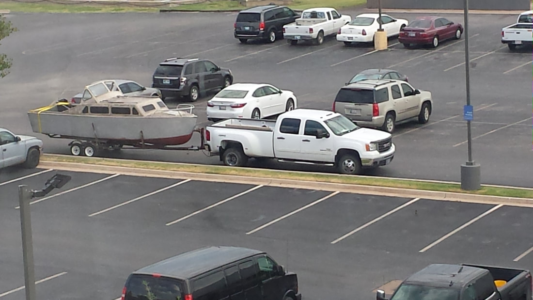
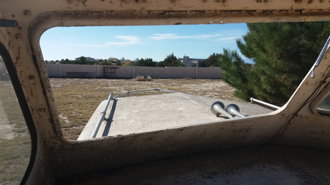
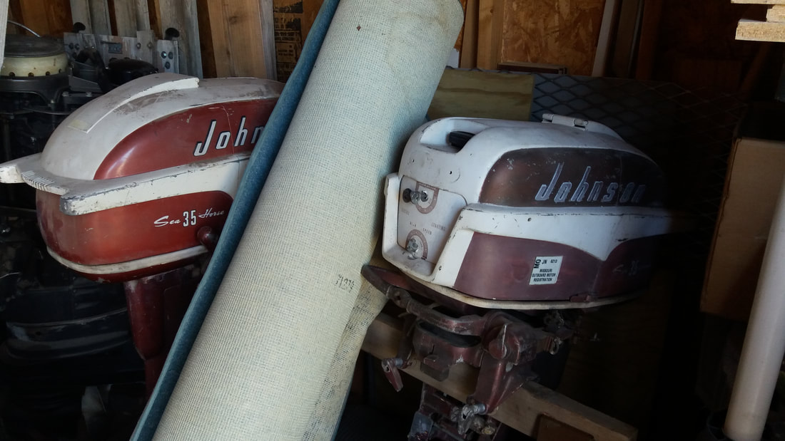
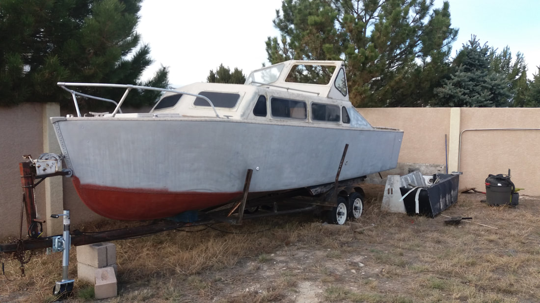
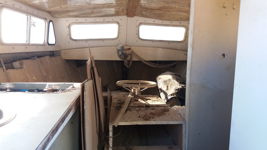
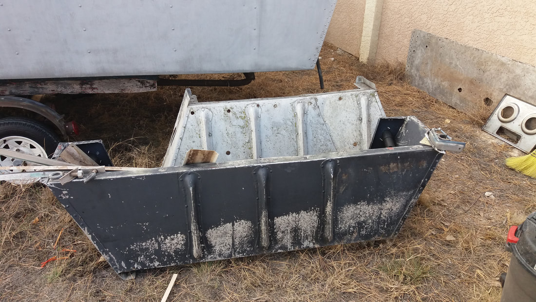
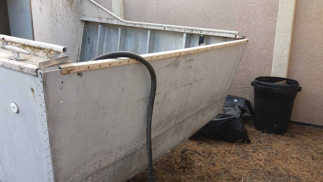
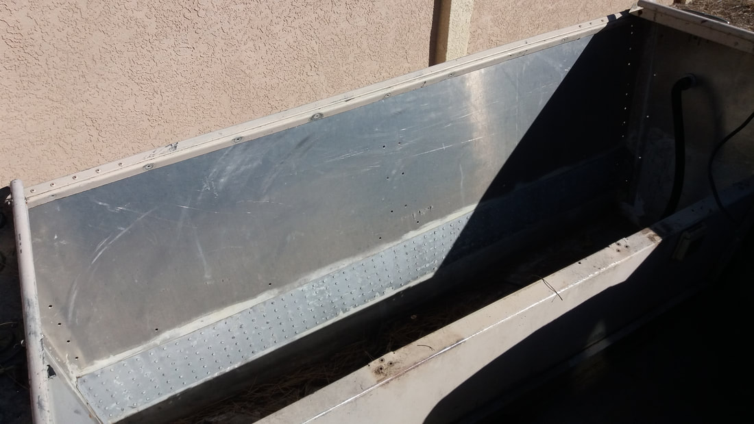
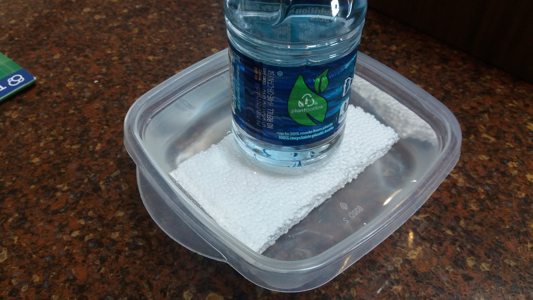
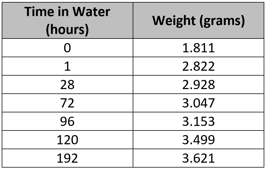
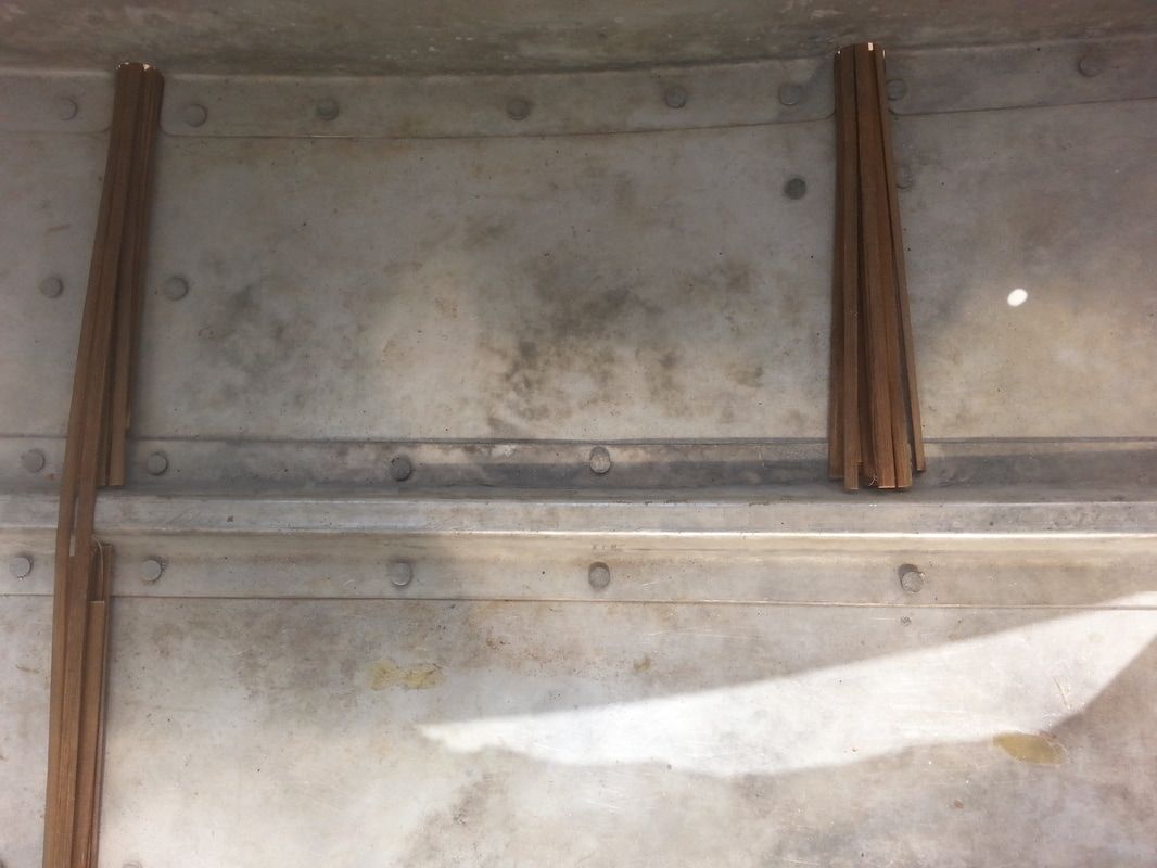
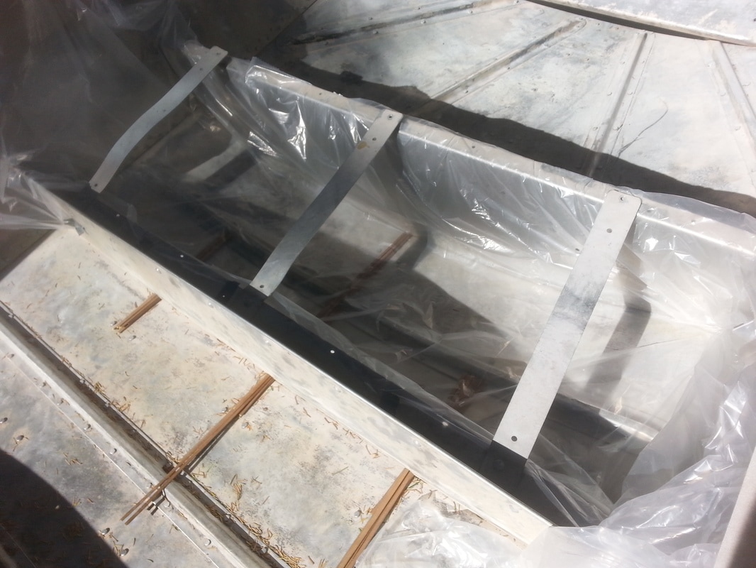
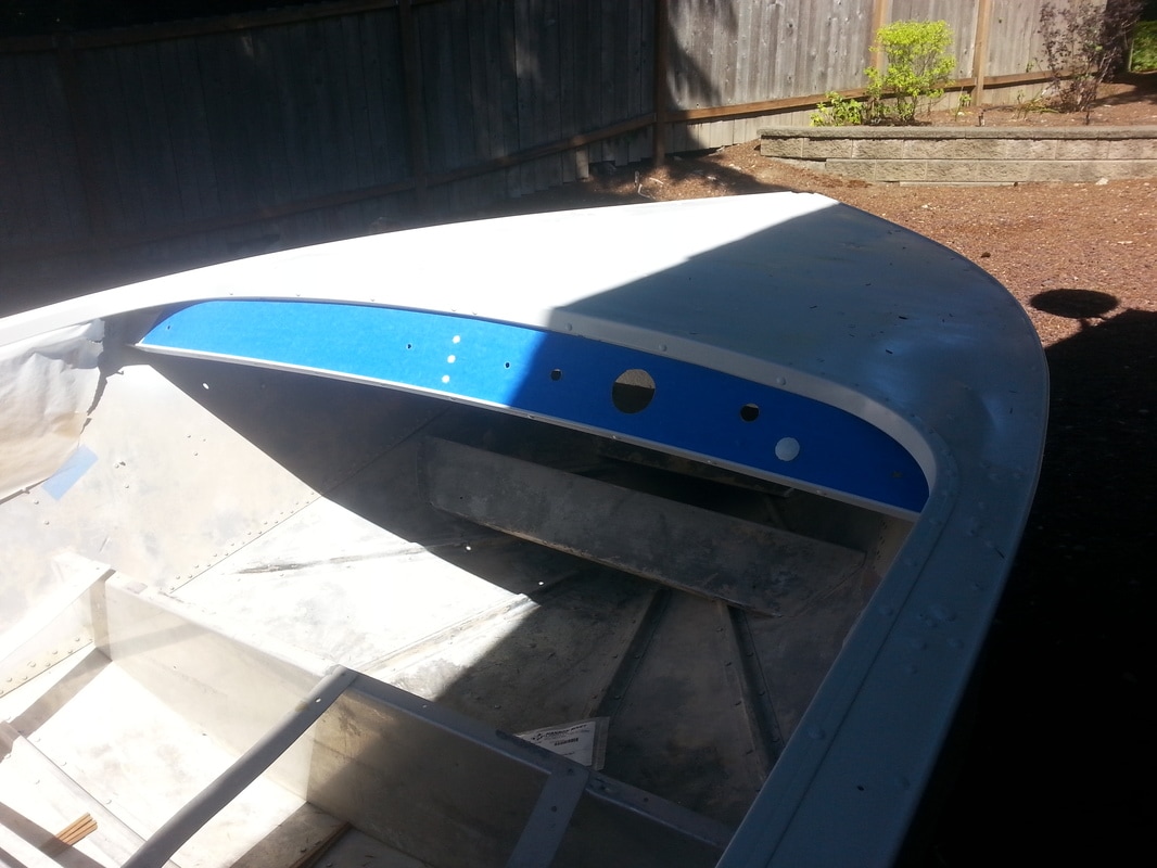
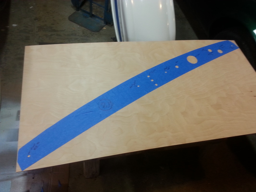
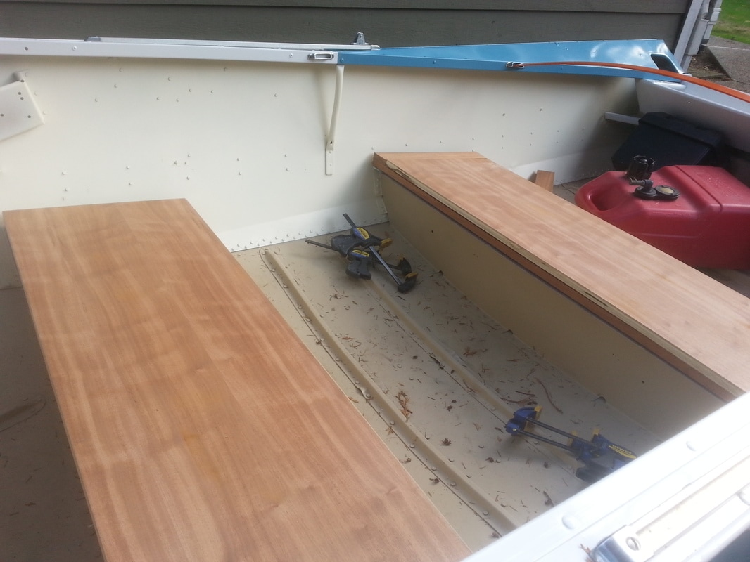
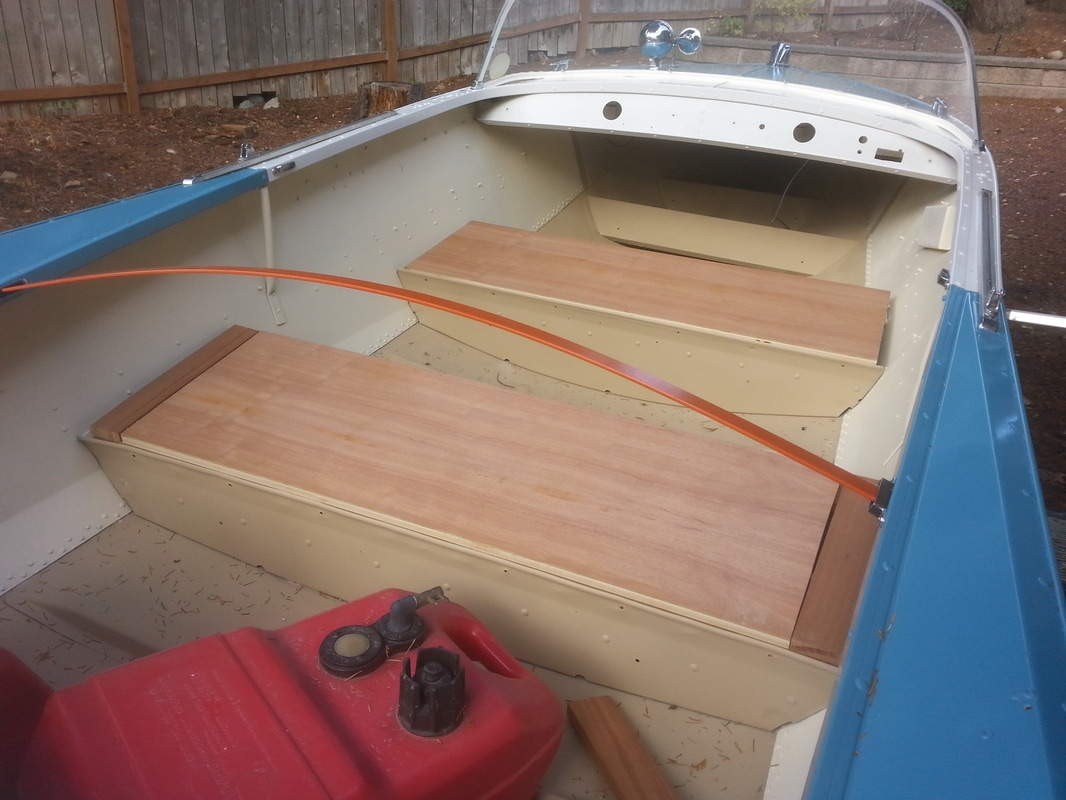
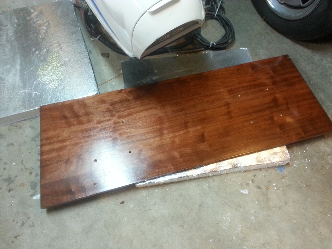
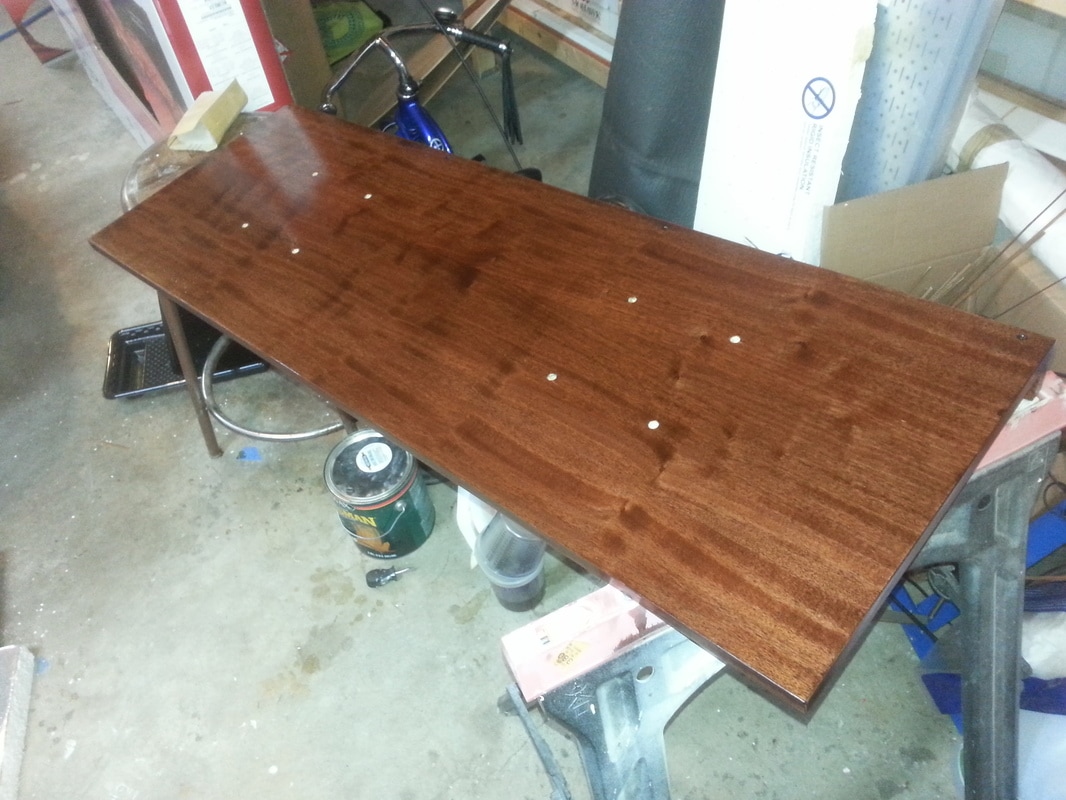
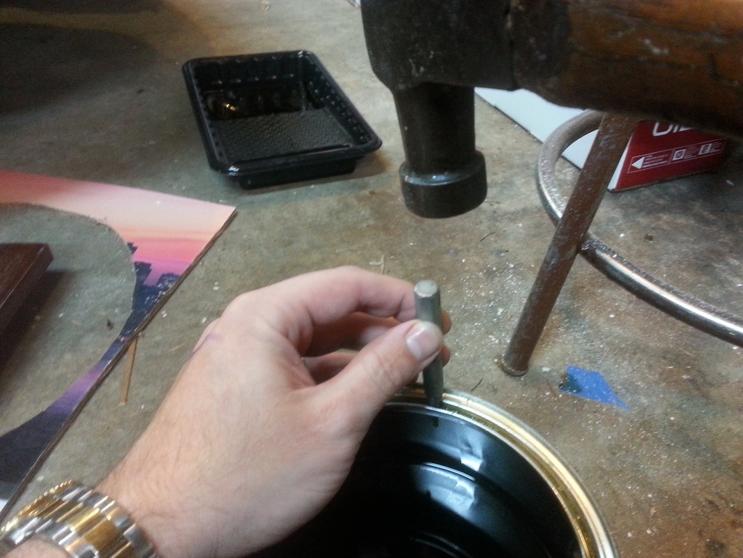
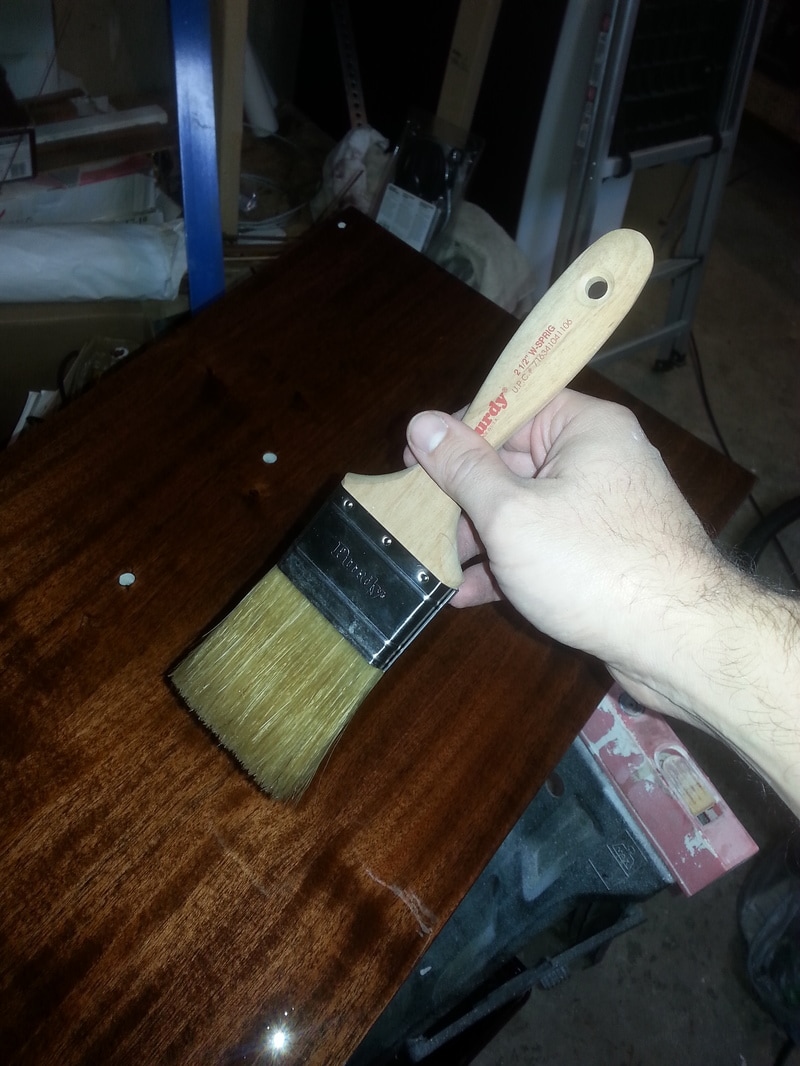
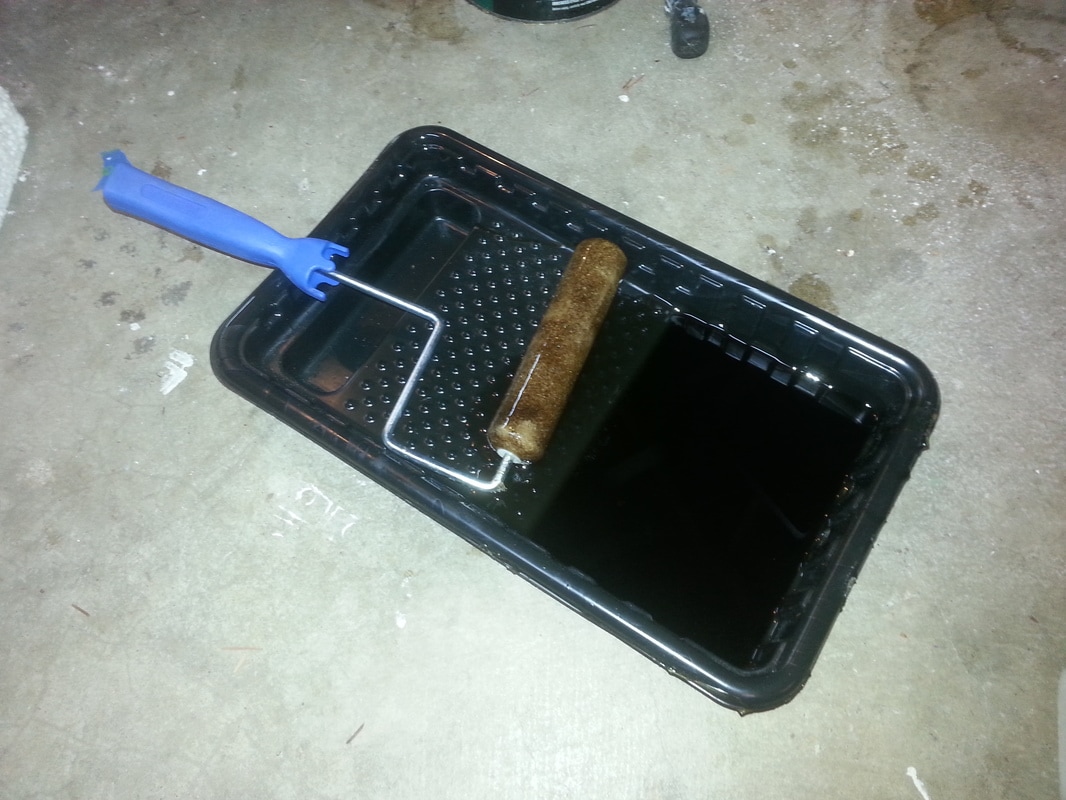
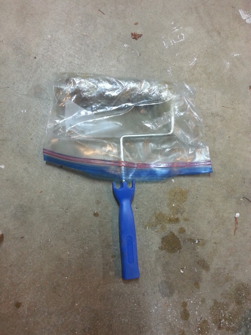
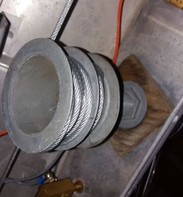
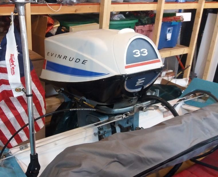
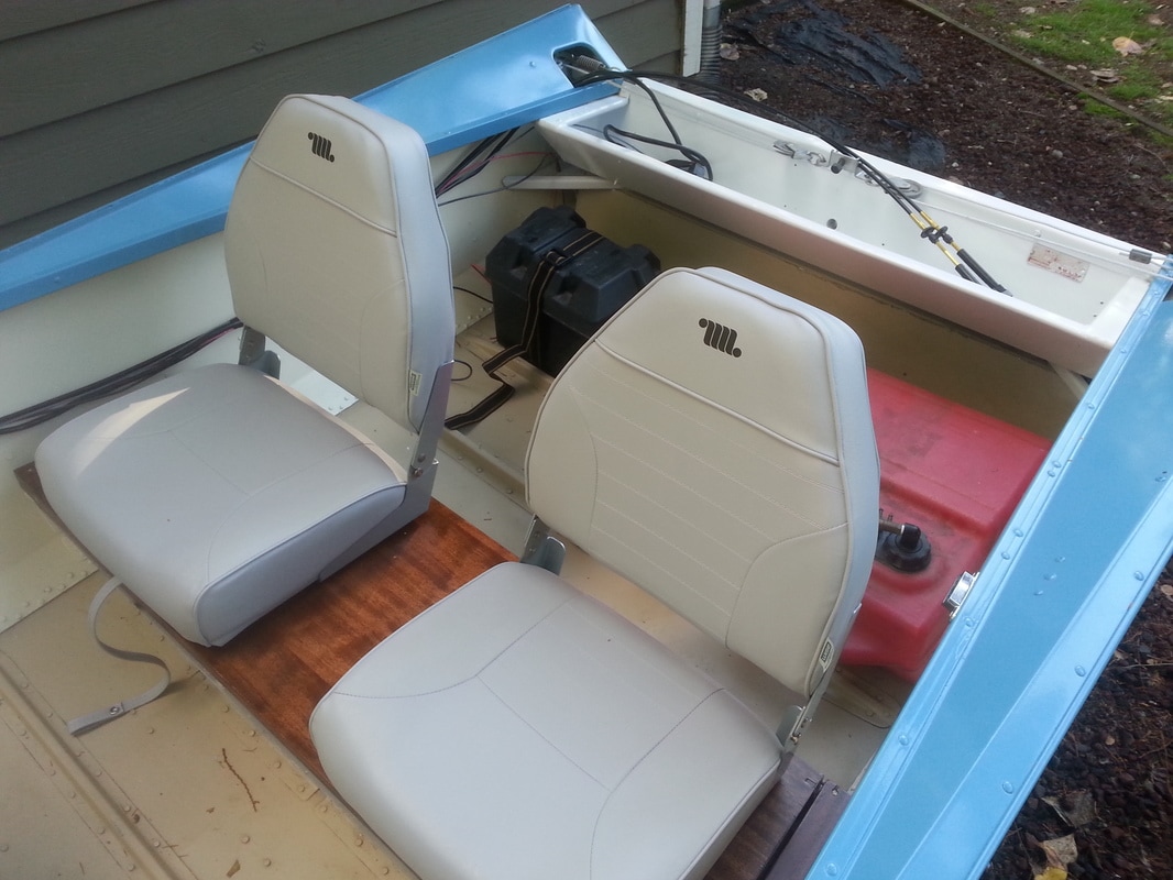
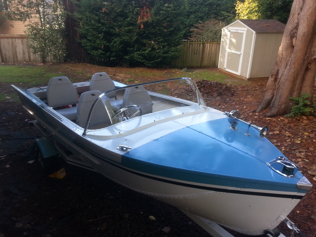
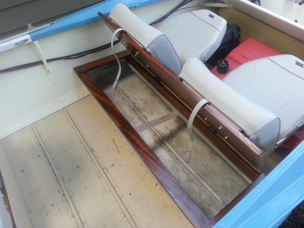
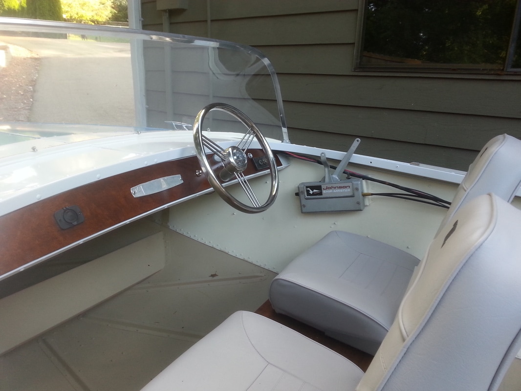
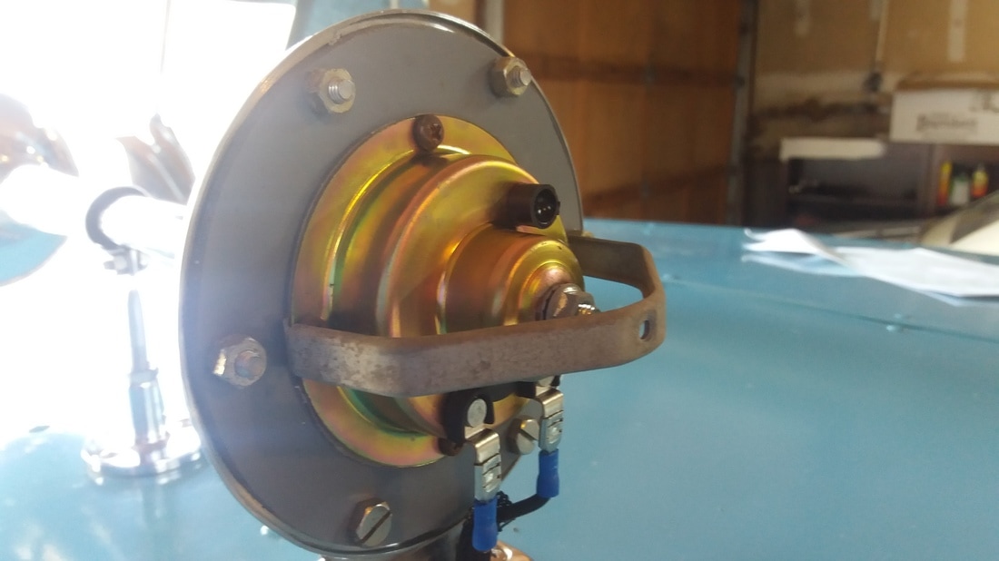
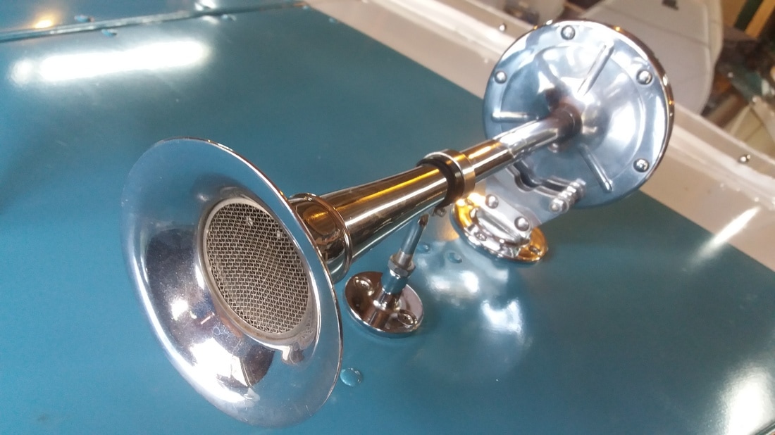
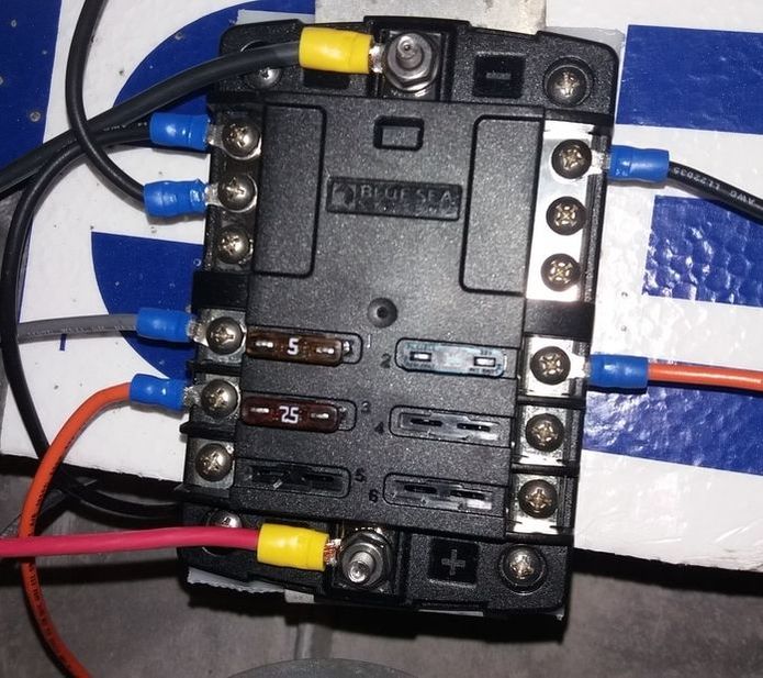
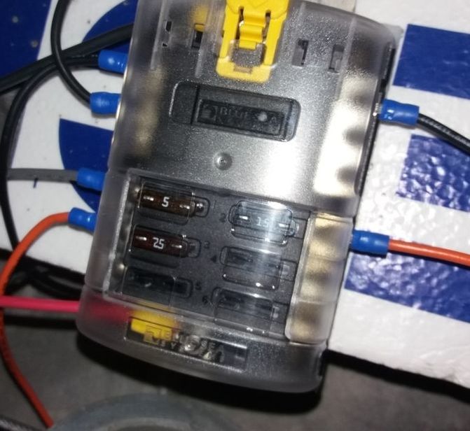
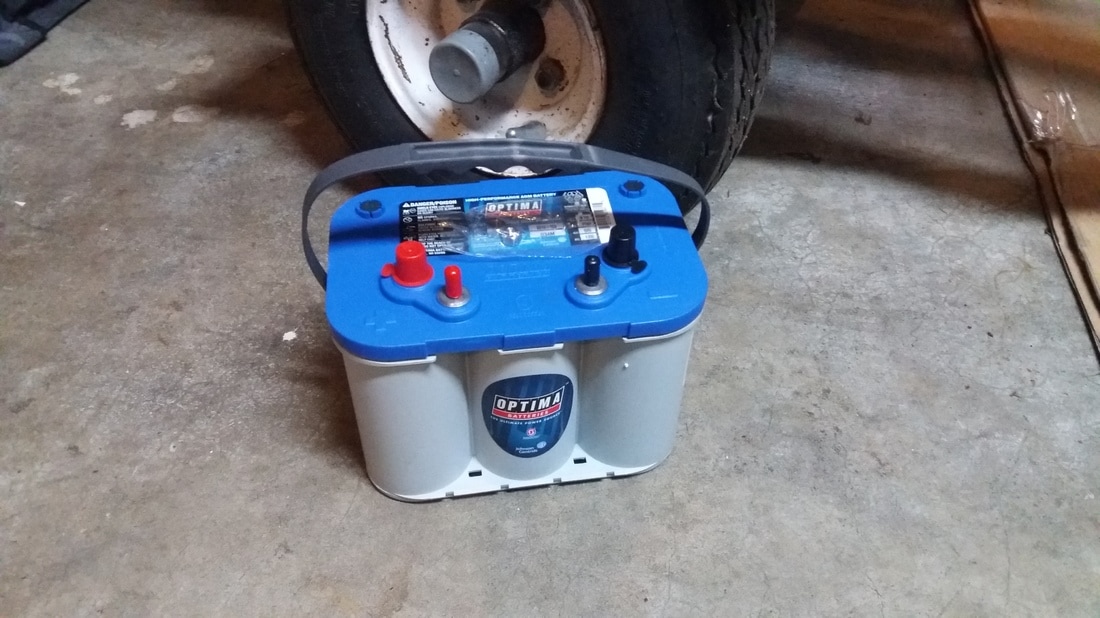
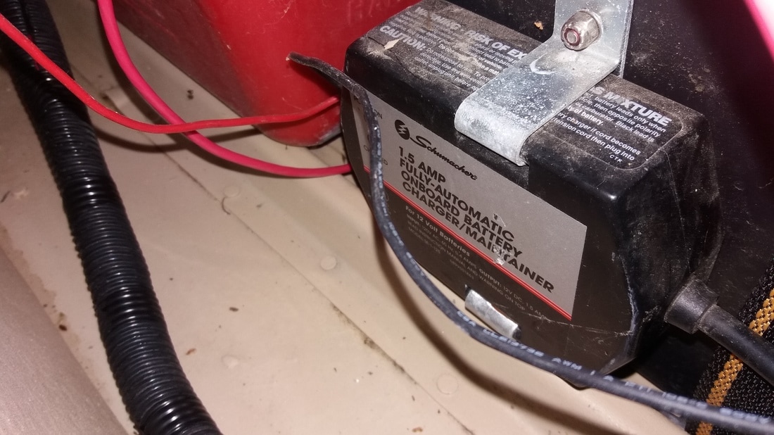
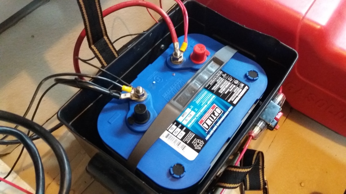
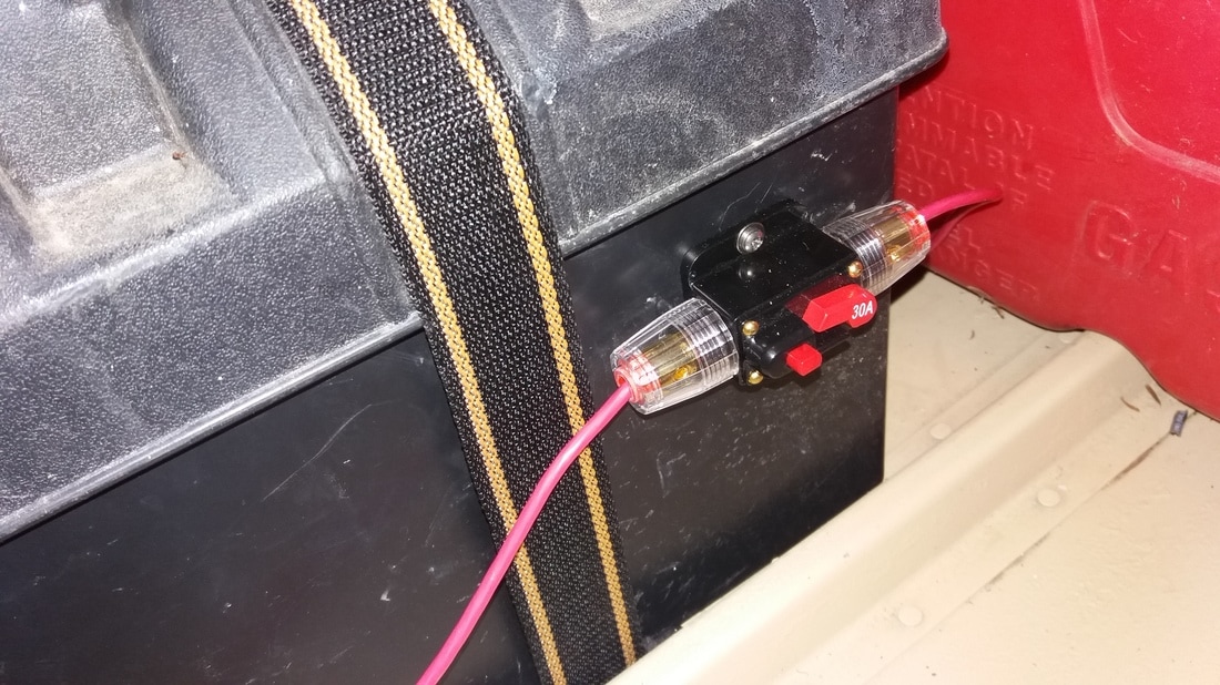
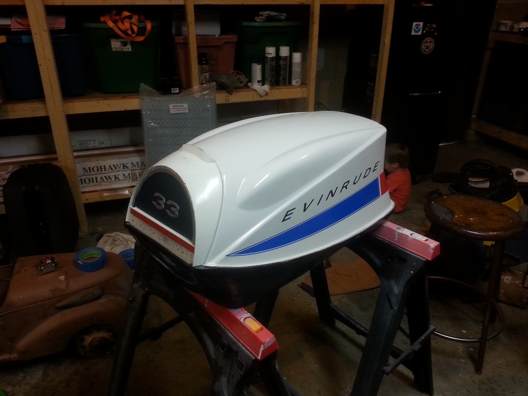
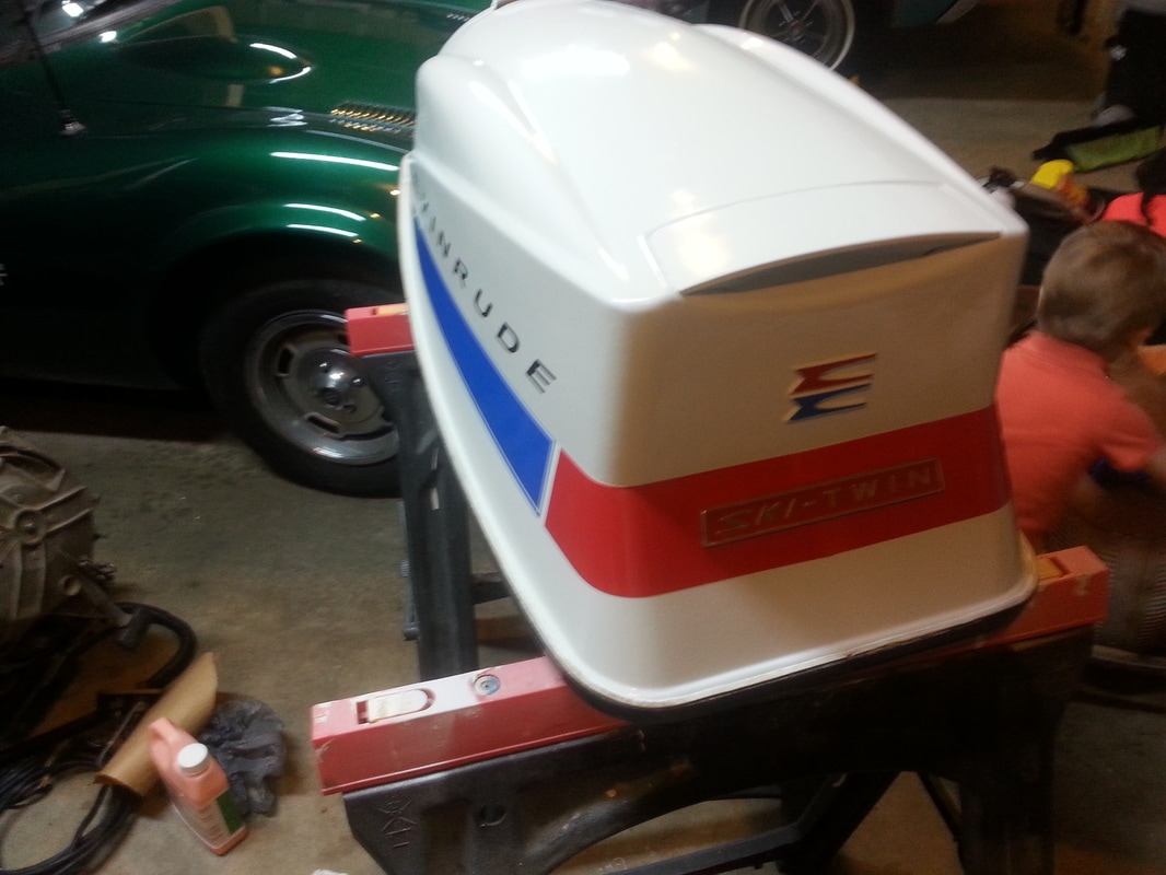

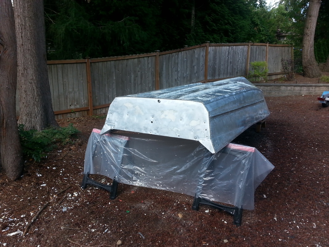
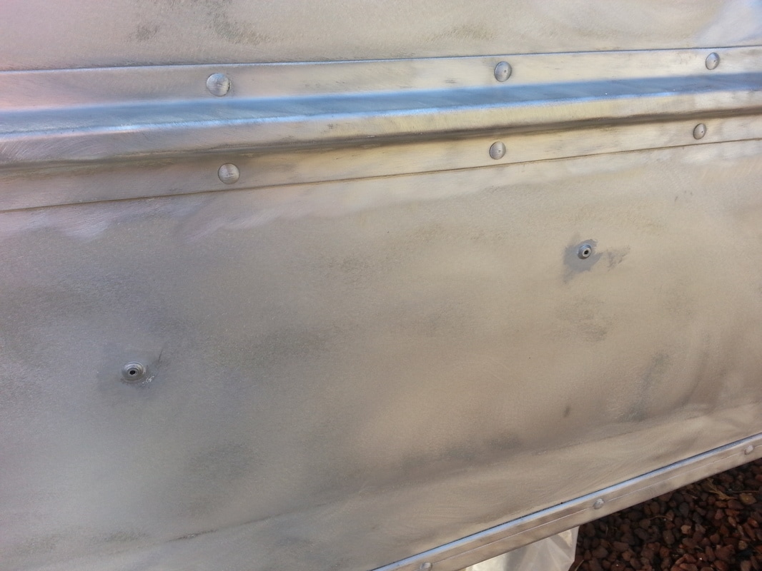
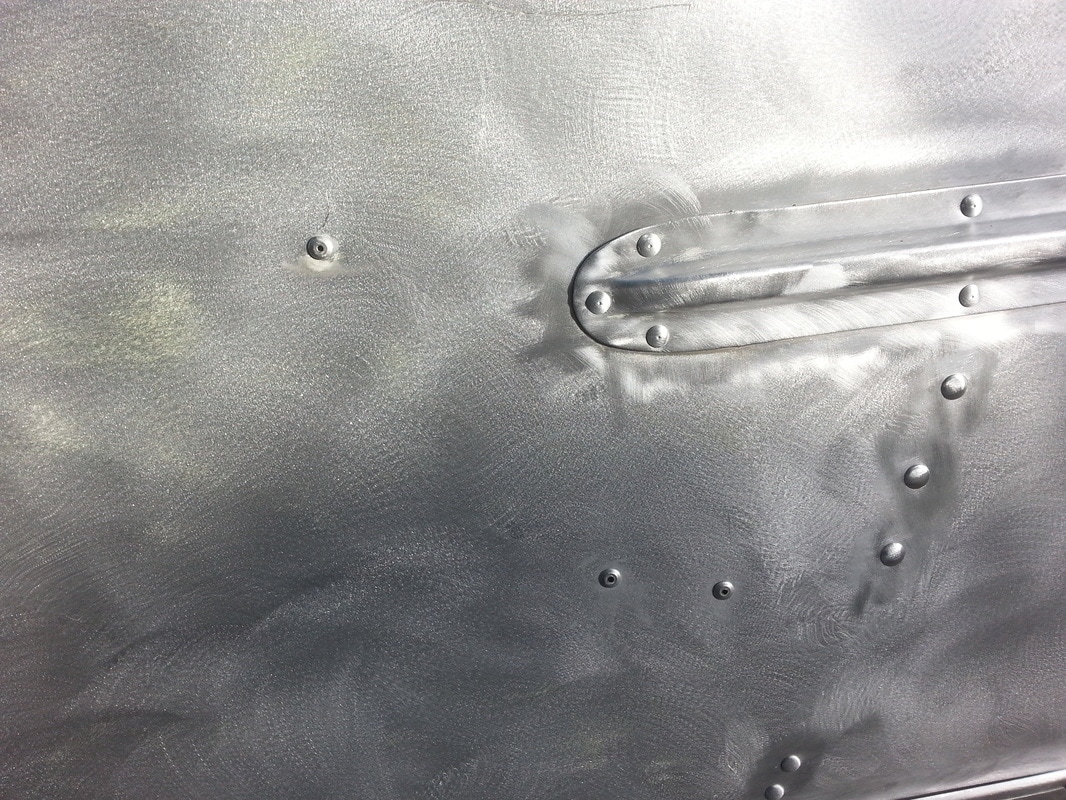
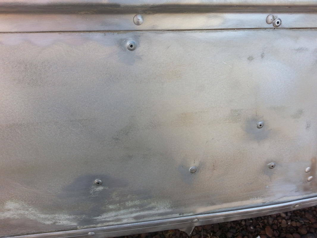
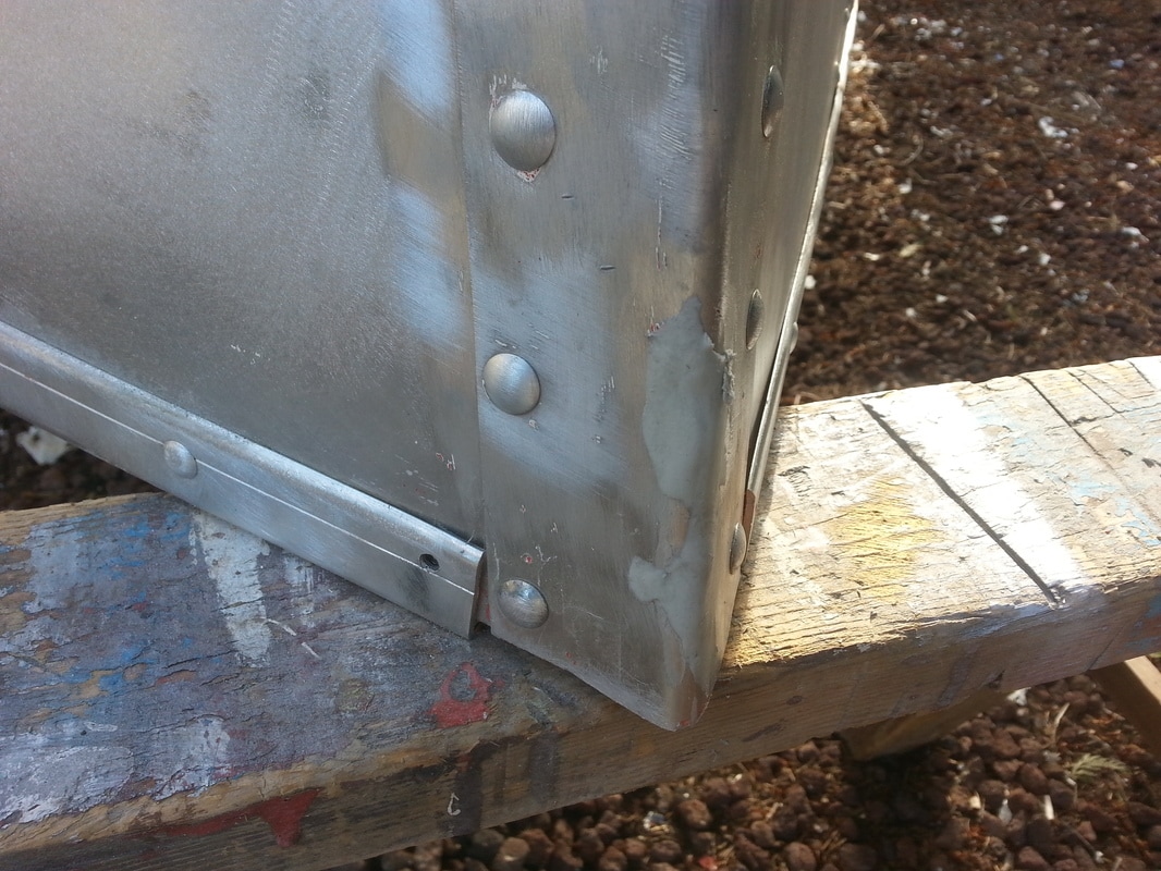
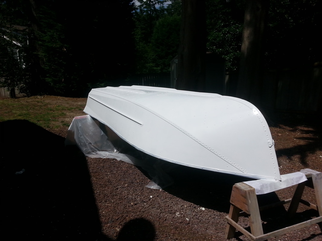
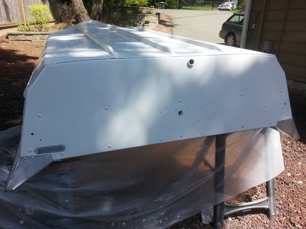
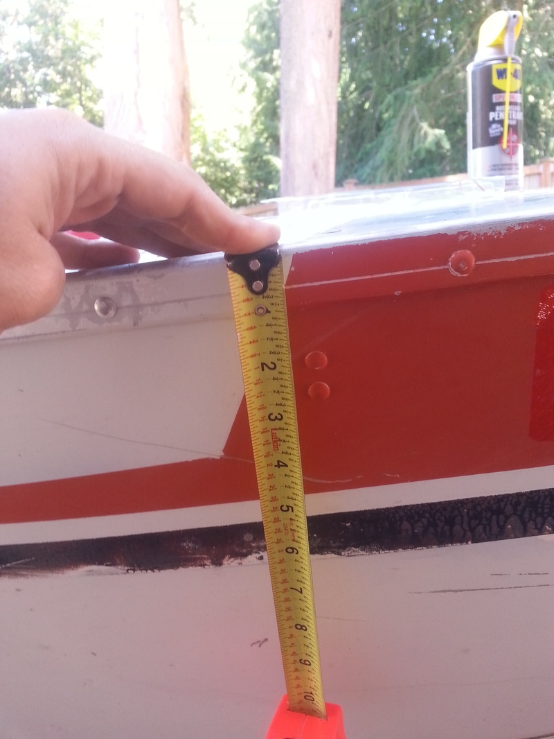

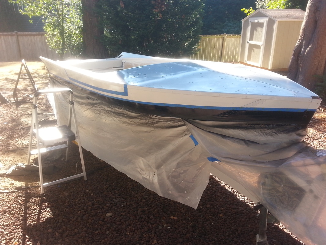
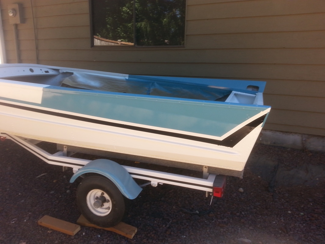
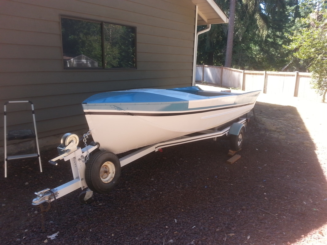
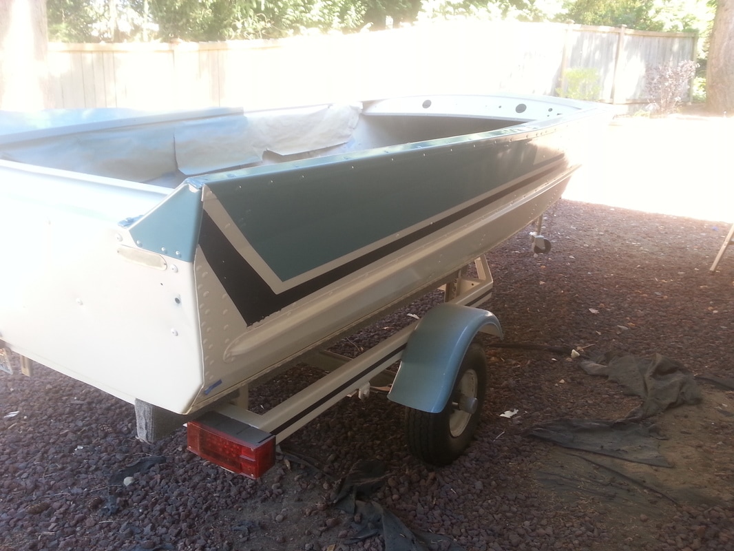
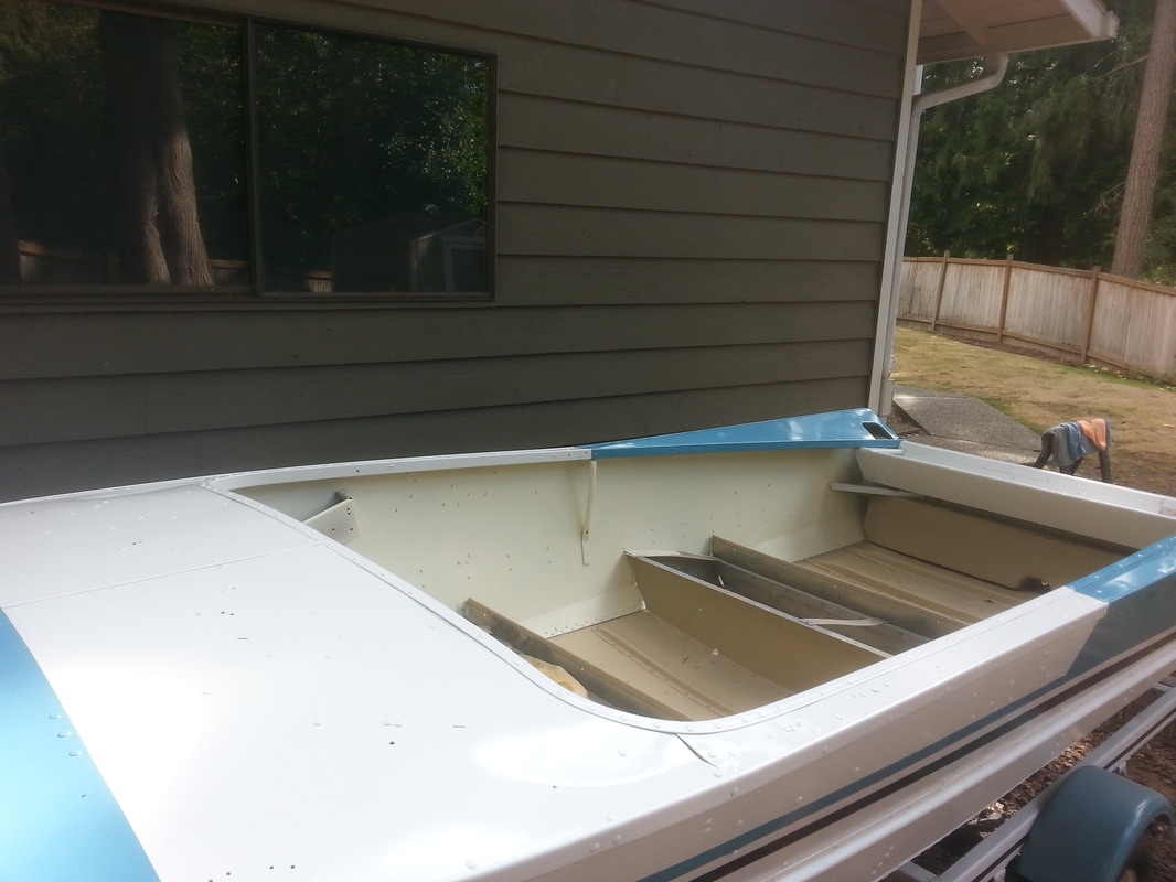
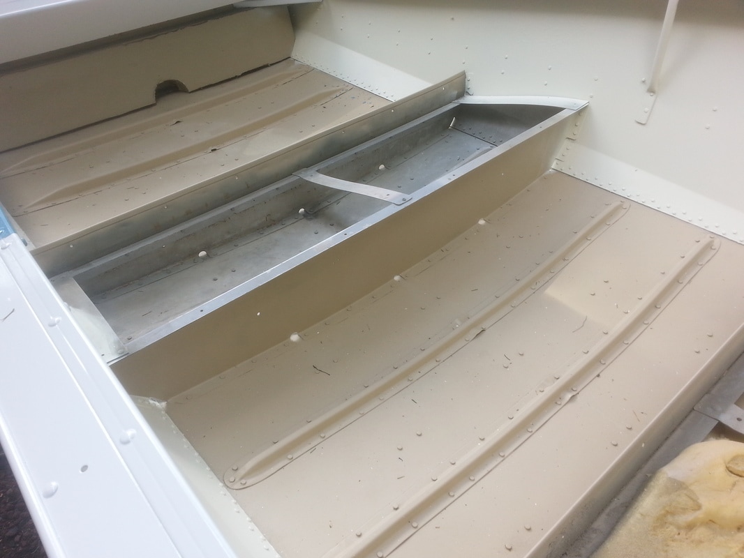

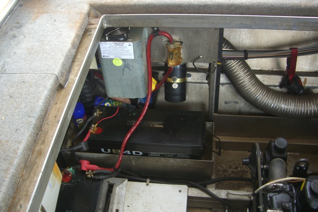
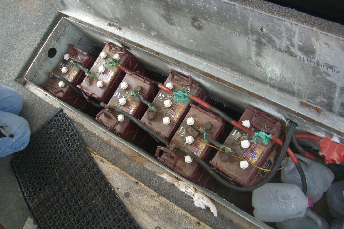
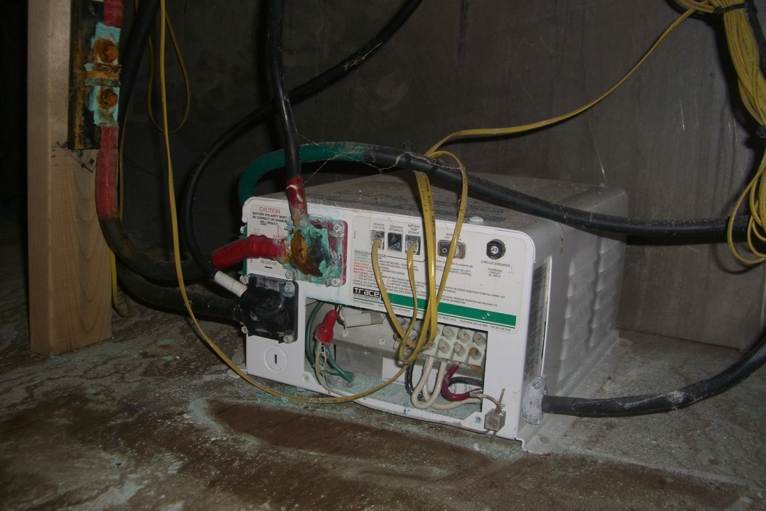
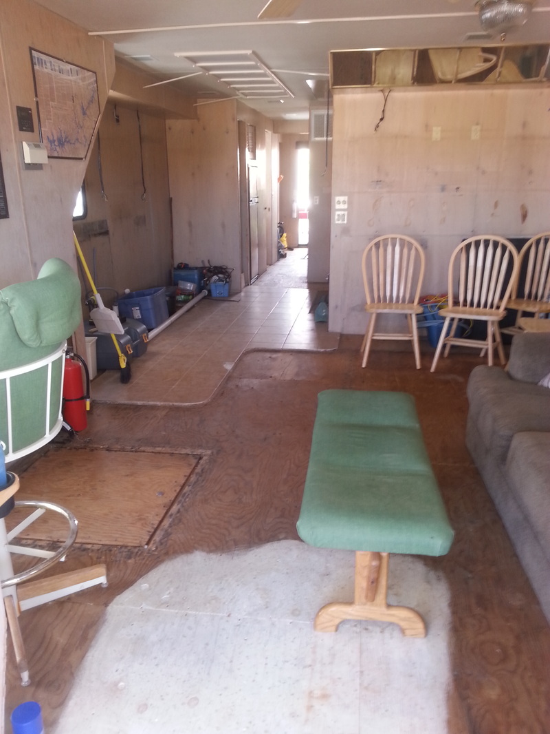
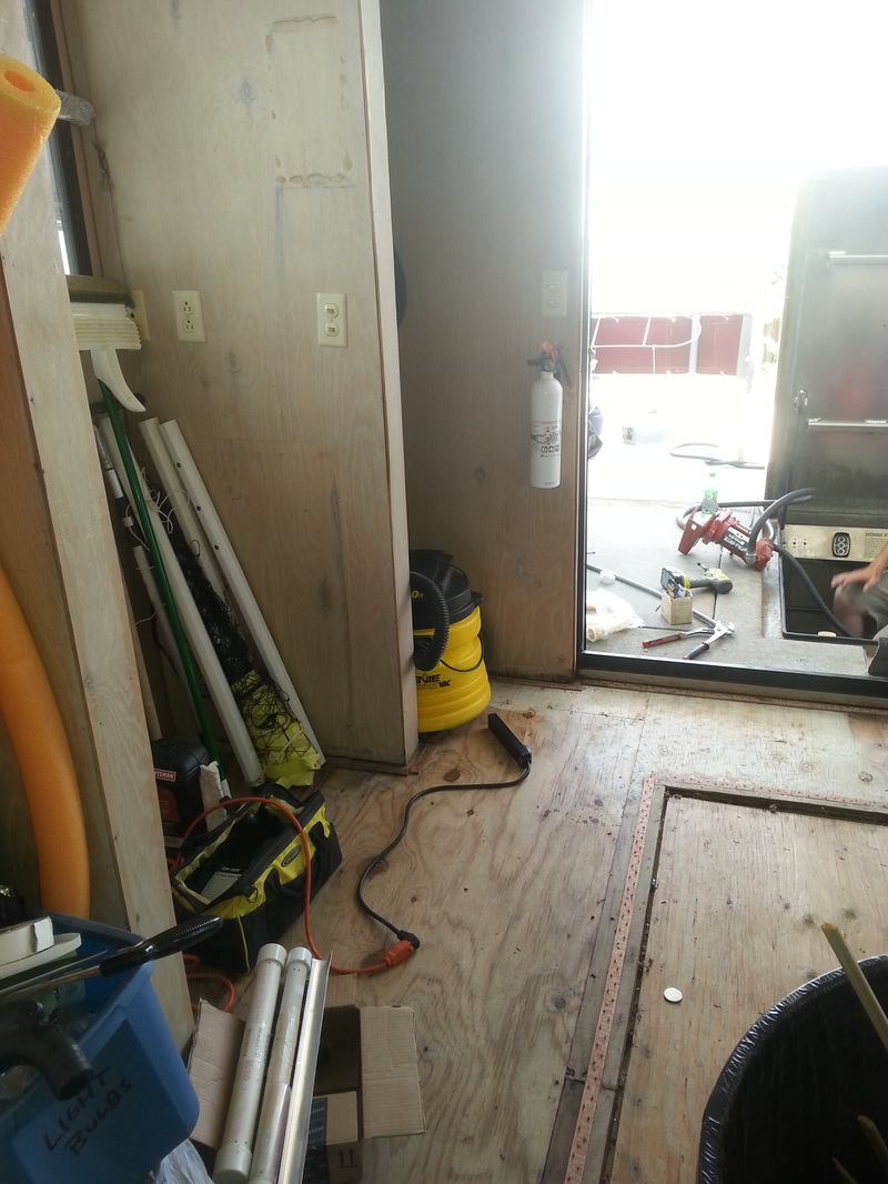
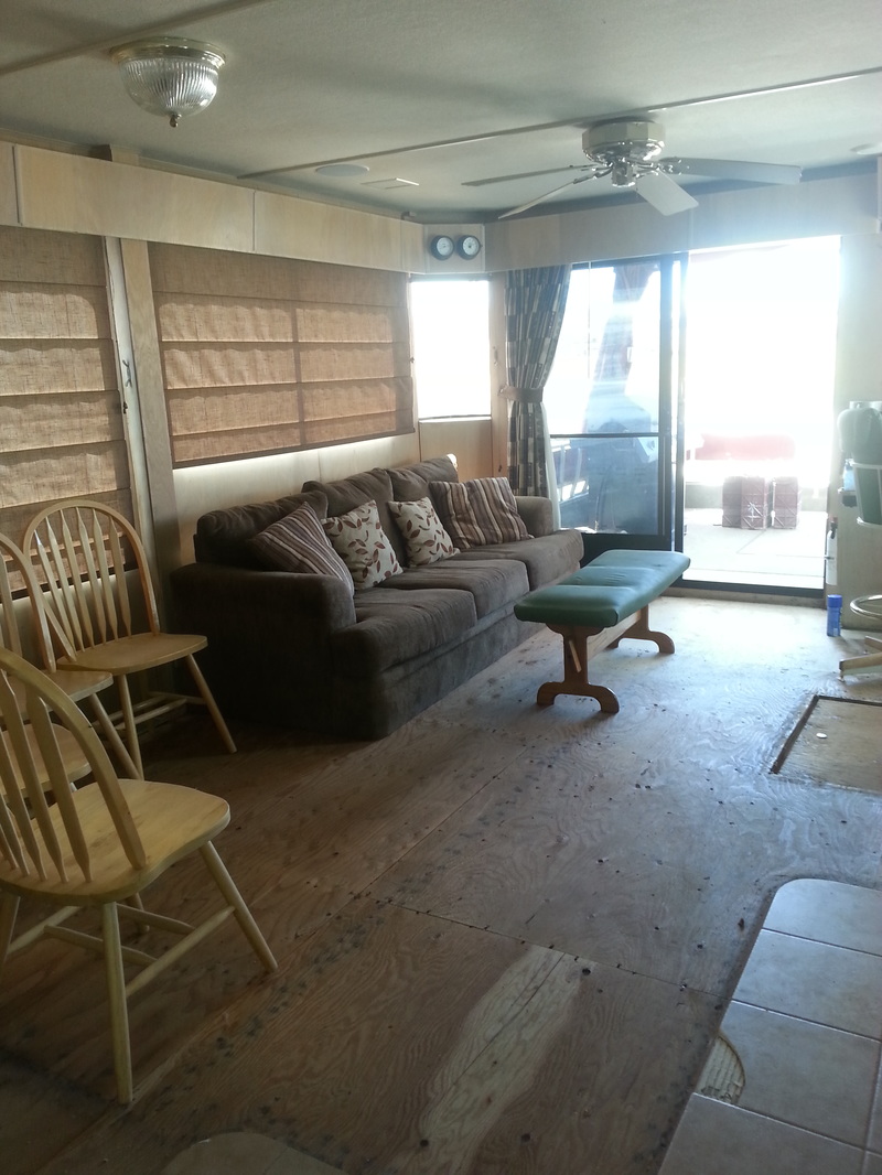
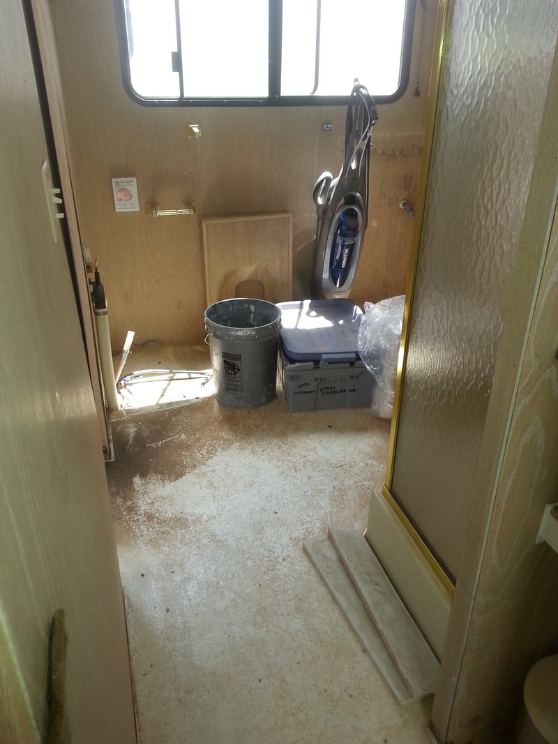
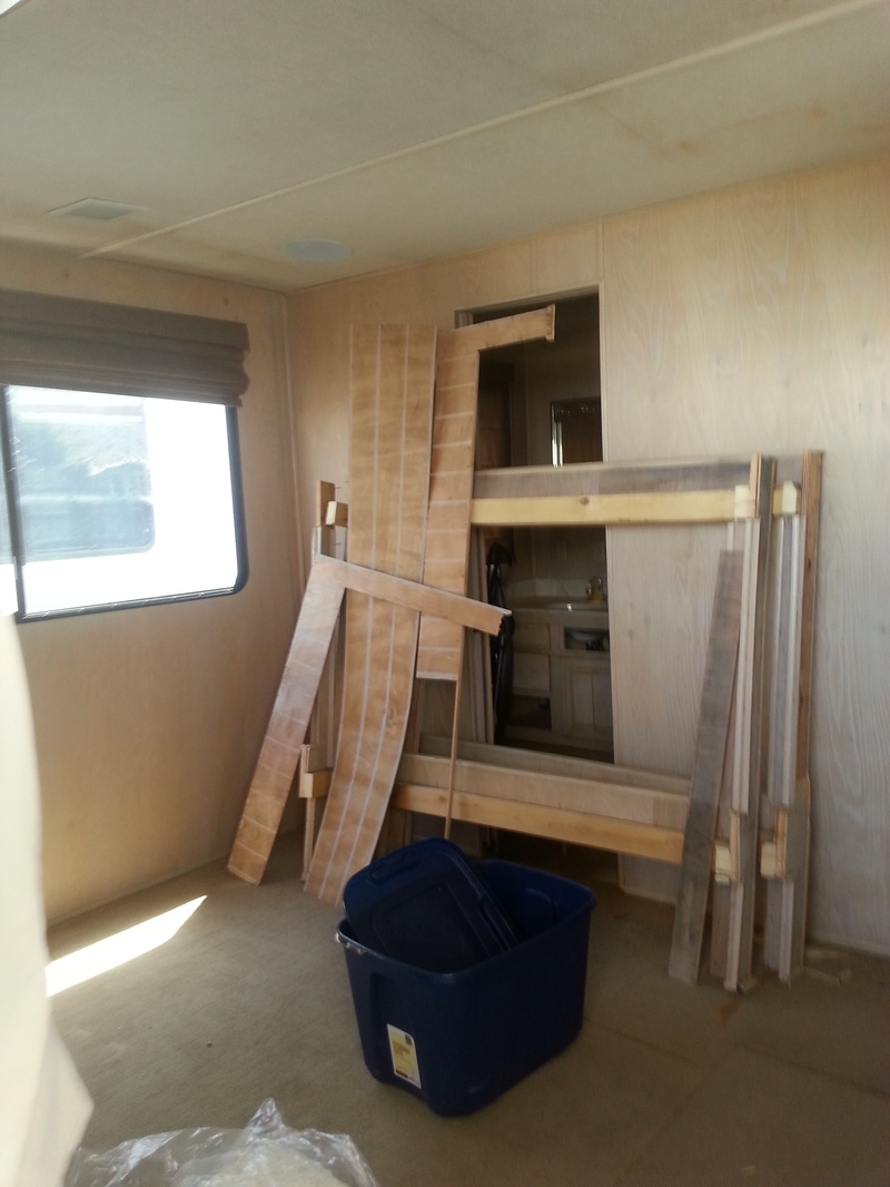
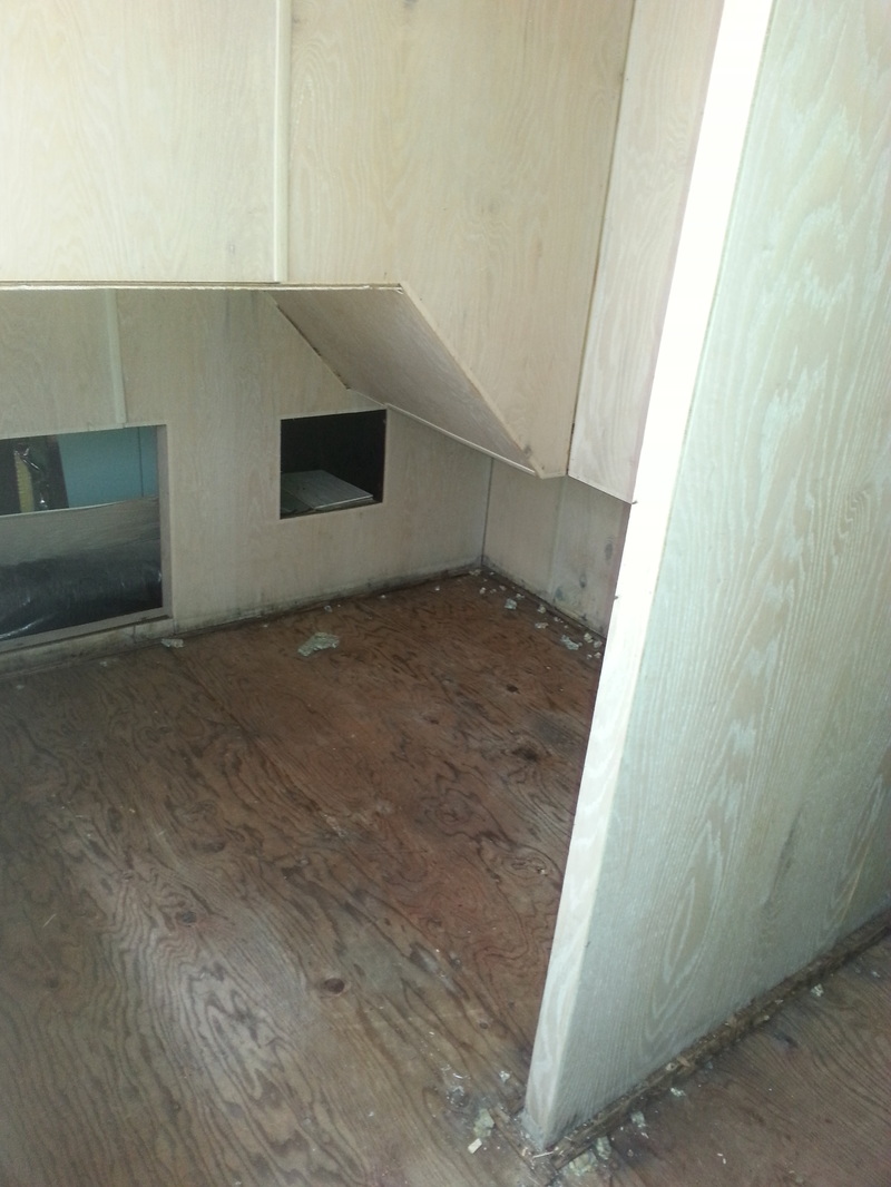
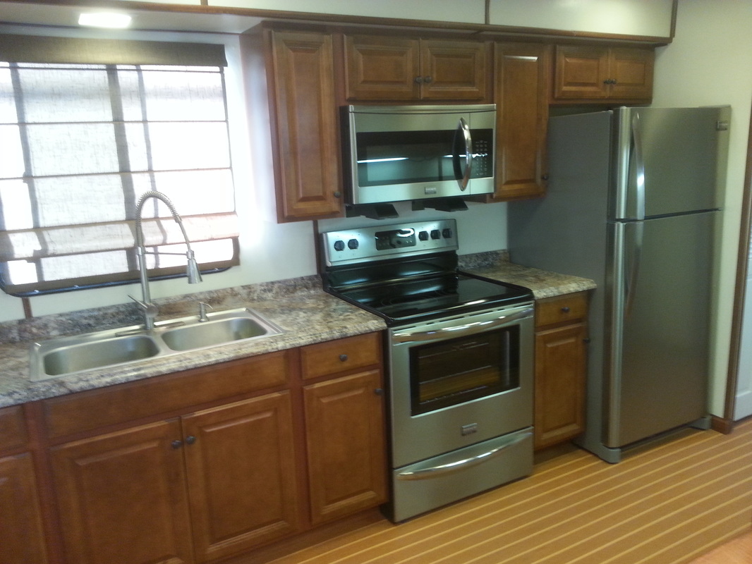
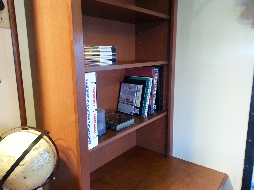
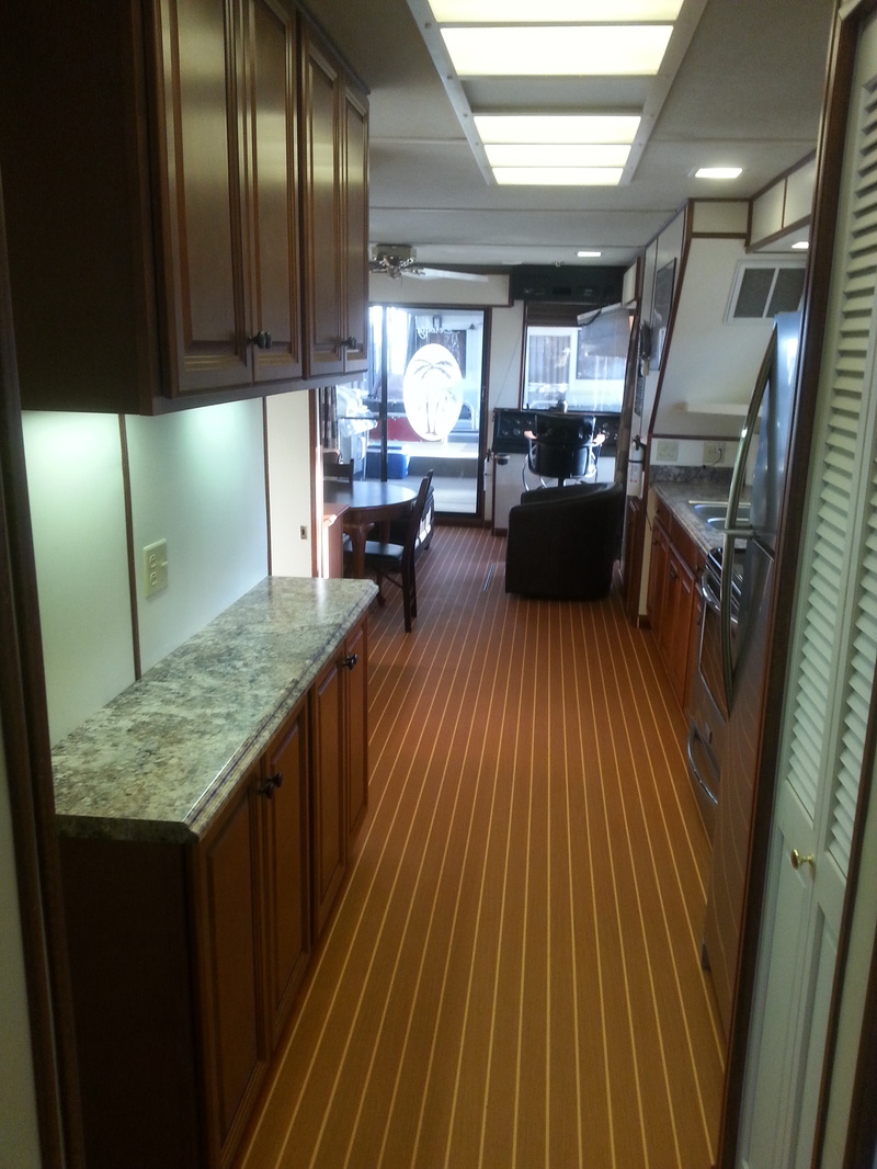
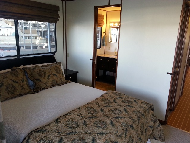
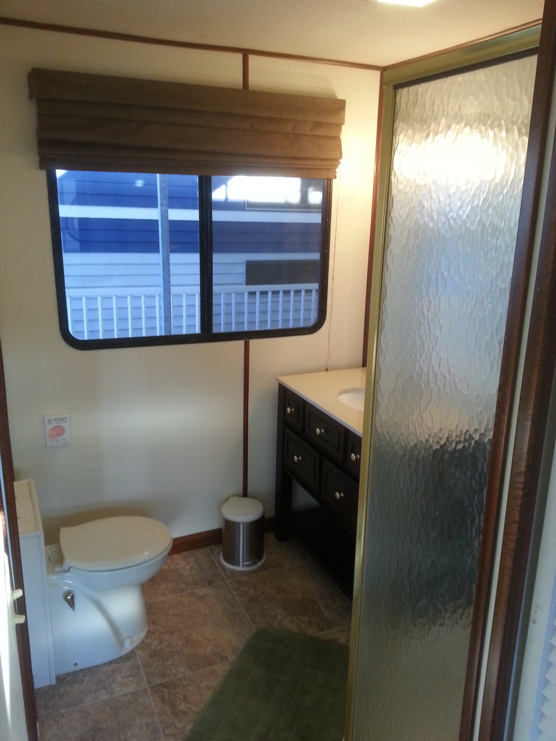
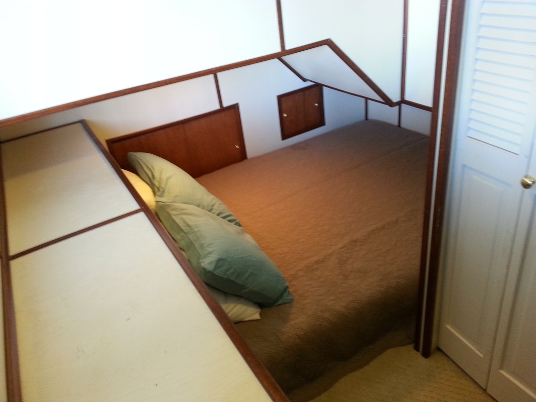
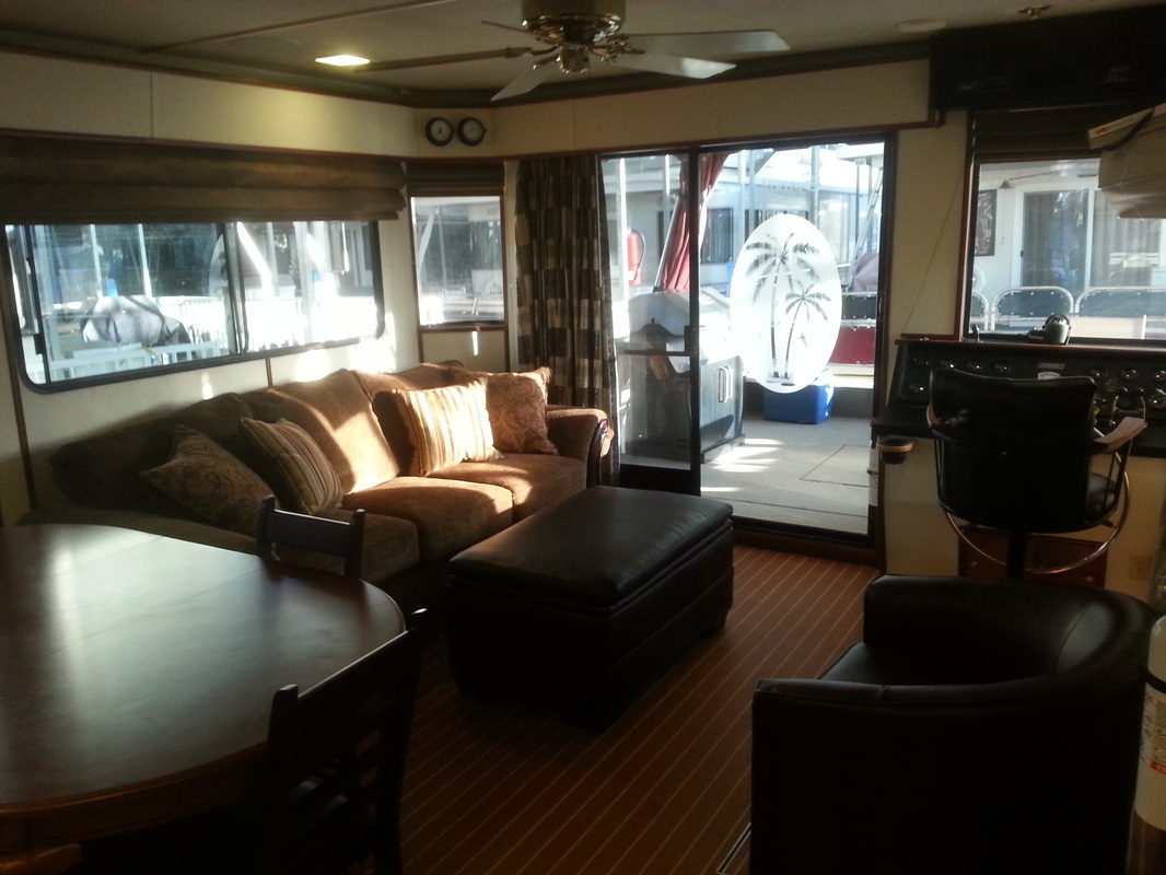
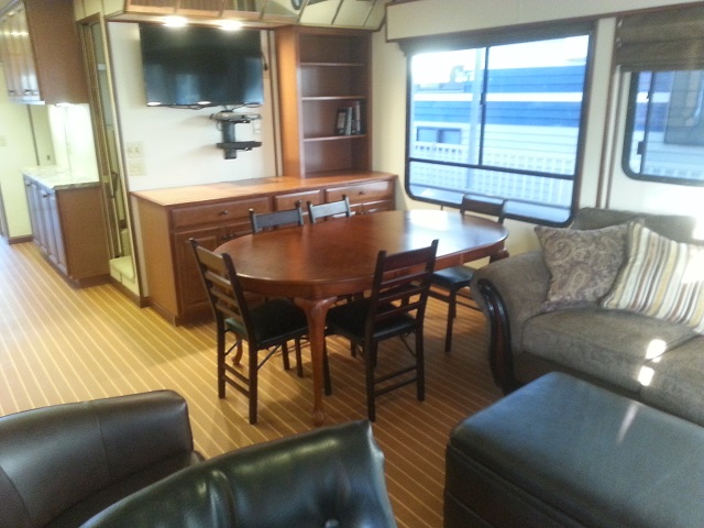
 RSS Feed