|
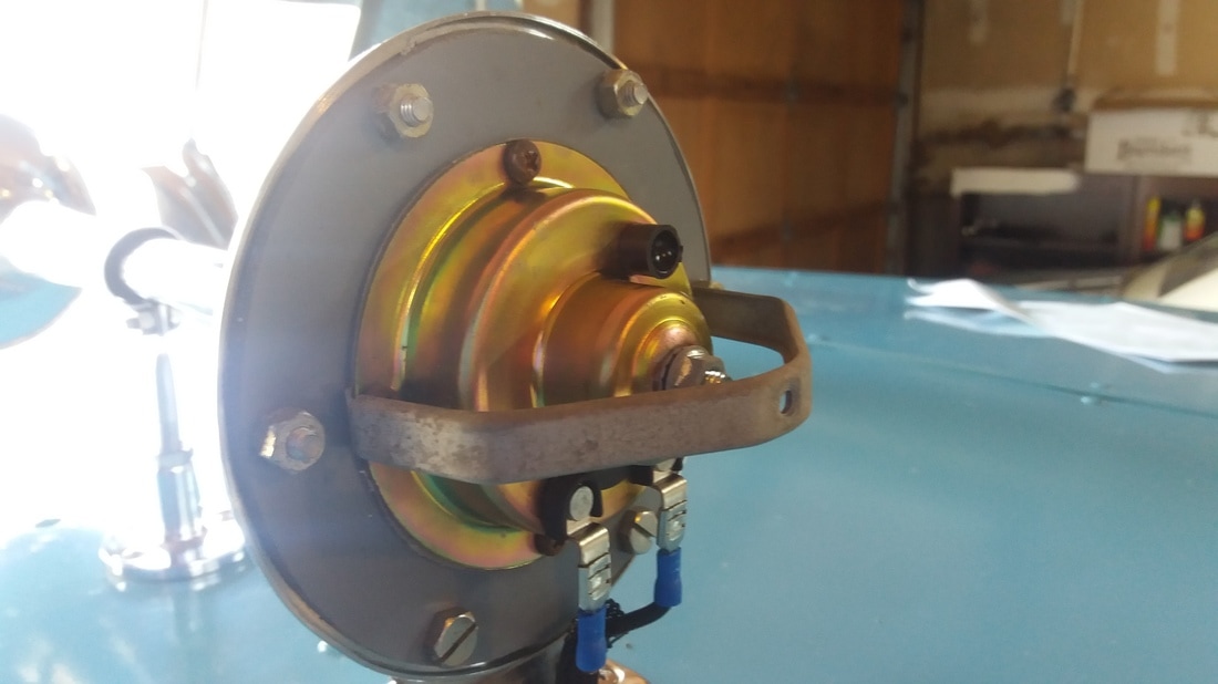
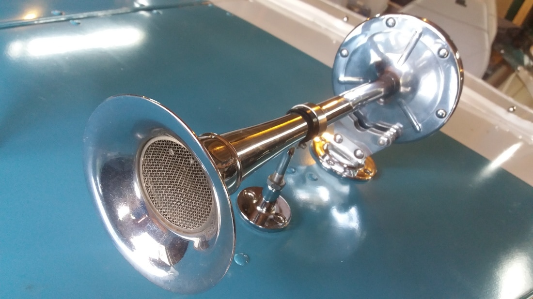
I know a lot of you are probably reading the headline to this post and thinking…Watt? (Insert rim-shot here) I know, electricity puns aren’t very Current, but they really get me Amped up. Okay, I’ll stop, since my wife insists that my puns Hertz her. If you haven’t guessed by now, this post is going to involve electricity and more specifically the rewiring of my Lone Star Malibu. As compared to a car’s electrical system, I find that wiring a boat is really quite simple…at least a small boat like this Lone Star, a houseboat is in a whole different category (see my previous Shocking Post). Though the same principles still apply, no matter how big the job. Electrical wiring should be taken seriously, and in the world of boats, as with electrical wiring in your home, there are rules that should be followed. The American Boat and Yacht Council (ABYC) writes the standards for the wiring in boats; manufacturers follow these guidelines rigorously, but owners can tend to flagrantly disregard them. I referenced the wire sizing guidelines in my previous post linked above, and the same still holds true for this post (make sure your wire is appropriately sized for the amperage draw and the length of the run). I won’t go into chapter and verse of the ABYC standards, but if you are tackling a wiring project, they are worth consulting to make sure you are using the correct materials and following convention. I will mention that there is a wire color code that should be followed for vessel wiring set by the ABYC. However, not all boats will follow this wiring color scheme, some manufactures used different wiring schemes as late as the 1990s and you can never be sure what a previous owner might have done. If you are rewiring your boat, it would behoove you to bring it up to the current standard. 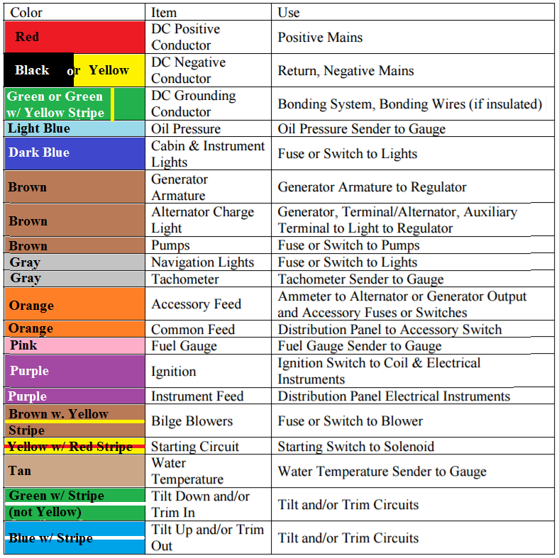 I used black for my ground and not yellow, which is quickly being phased in by manufacturers after the 1996 update by ABYC so that there was no confusion between the DC system ground and the AC system hot wires. I went with black since I had it on hand and don’t have to worry about an AC system on the Lone Star (the houseboat got the same treatment since that was the color scheme already in place). The first thing I had to do was make sure I had all my components in working order. I rewired the bow light and converted it to an LED bulb. That was fairly easy, I just pulled it apart and replaced the bulb socket with a new one that I purchased on eBay and purchased the corresponding LED bulb. I likewise refurbished a vintage stern light that I purchased on eBay with an LED bulb and a new mounting base to fit the narrow mounting surface I was left with because of the fins at the stern. 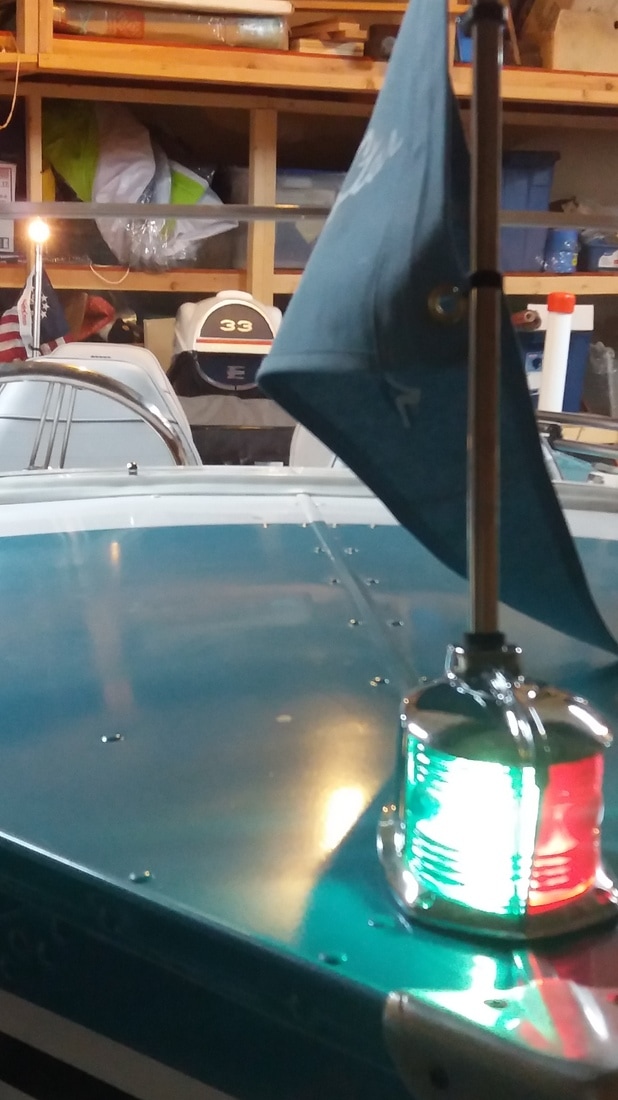 I also had to rebuild the horn, which was a slightly more involved process. I first tried to get the old horn working, but to no avail. Powering it should turn on and off a magnet very quickly to vibrate a metal diaphragm to produce sound that was amplified by the horn body. No amount of cleaning would get the mechanism working again and I was forced to look at other options. I ended up buying one of the cheap horns from Harbor Freight and pulling out the innards (diaphragm, actuator, etc.) to use in the old horn body. It wasn’t a perfect fit, so I got a 1/8-in thick piece of PVC and cut out an adapter to mount the new diaphragm on and then mount that onto the old horn body. I was thrilled when I applied power and it sounded like a horn once more.
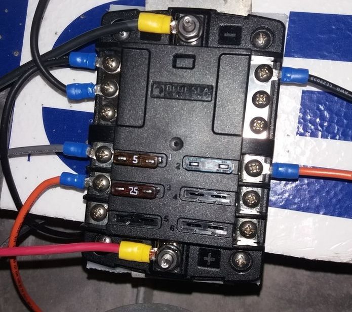
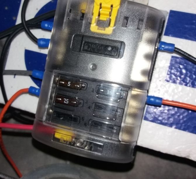
The only other components that I had were the new 12-V power outlet that I installed on the dash and the outboard motor, which came wired with its own harness. I’d just have to connect the outboards power cables to the battery and run the supplied wiring harness to the key and choke switch up front. Now on to wiring. Normally, I’m an advocate for using a switch panel with integrated breakers, like the one pictured below. I prefer breakers to fuses, since you don’t have to worry about carrying replacement fuses, and the panel places the fuse conveniently by the switch. That can eliminate a lot of headaches with figuring out which fuse goes with which switch goes with which accessory. 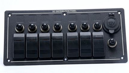 In the case of the Lone Star I wanted to have an original look and couldn’t picture a modern switch plate anywhere on the boat. As a result, I had to opt for a fuse block to run all my electronics. I suppose if I had really wanted to keep the fuses or breakers with the switches, I could have drilled corresponding holes next to the switches and installed a fuse holder or standalone breaker. I wanted a cleaner look though, so this fuse block was the best solution.
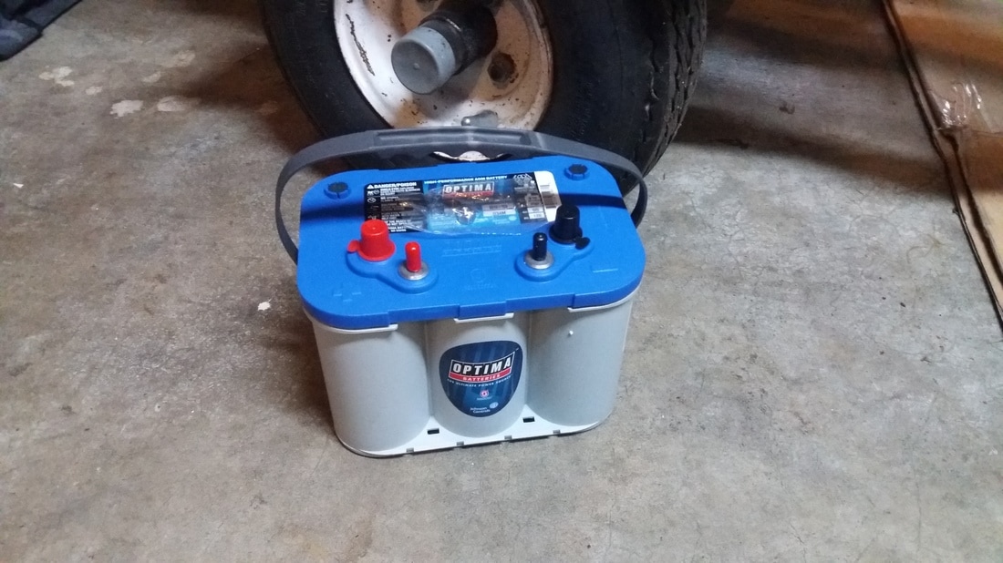
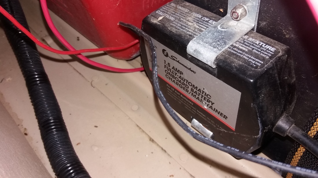
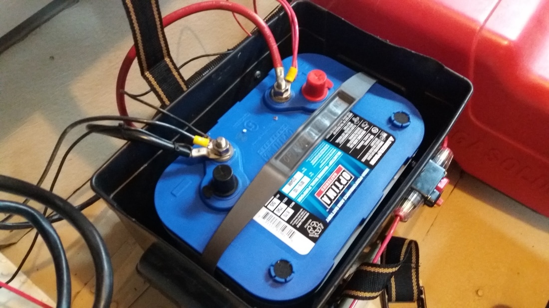
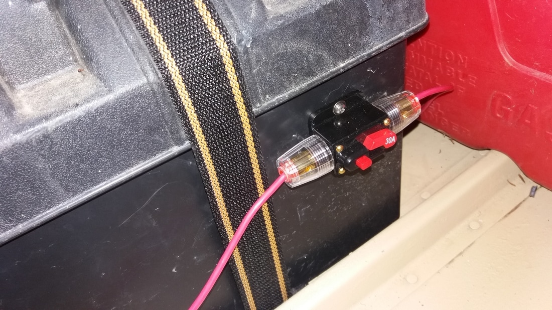
As I said, the wiring for the Lone Star was pretty simple, with just 4 components to supply. You’ll notice that I got a 6-circuit fuse block even though I’m only using 3 of them; leaving room for future expansion is always a wise decision. I don’t think I will be adding anything to this boat, but you never know. I might decide I want a radio, a fish finder, a VHF, a chart plotter, etc. There's no end to the things you can spend money on adding to your boat (a hole in the water you throw cash into), so you'll never regret leaving room for later expansion. Now, on to the wiring. I made up the below wiring diagram with the actual wire colors I used (black for ground, red for supply, gray for navigation lights, and orange for the horn and 12-V outlet), but I thought that color coding each component made it a little easier to read (bow light = purple, stern light = green, horn = blue, 12-V outlet = orange, 12-V positive supply line = red, and grounds = black ). 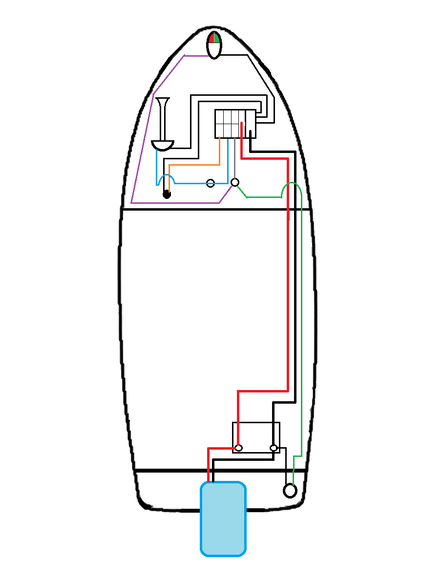 I bought myself an Optima BlueTop battery, which is an AGM (Absorbed Glass Mat) battery that is designed as a starting and deep cycle battery. It is sealed and maintenance free; it’s rated for 750 cold cranking amps (number of amps the battery can deliver at 0°F for 30 seconds while maintaining a voltage of at least 7.2 volts) and had a capacity of 55-Ah (you can draw 1-amp for 55-hours, or 55-amps for 1-hour, or something in between). I just had to give that battery a nice home. I got a battery box and mounted the strap down to a couple of ribs with the battery box sitting in between those ribs. I also mounted a battery trickle charger to that box, so that all I would have to do to give it a charge before heading out to the lake is plug it in. I also mounted a 30-amp breaker to the outside of the box and ran a 10-ga supply line through that and up to my fuse block along with a 10-ga negative line to the integral negative bus bar.
From the fuse block, I ran 12-ga wire for each of the components. The 12-V outlet was wired directly from the fuse block, fused at 20-amps. The horn was wired through a momentary push button and fused for 7.5-amps. The navigation lights were fused at 5-amps and run through a three position plunger style switch, which has one output terminal energized in the first on position and both output terminals energized in the second on position. That allows you to energize just the stern light to act as an anchor light, or energize both stern and bow lights for your standard running lights. 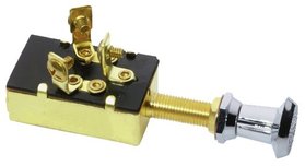 I should mention, if you’re wiring navigation lights with a rocker switch (like the switch panel I prefer above), you will need a double-pole double-throw (DPDT) switch. Run power to the input terminal of both poles, on one pole you can connect the two output terminal and run a supply line to the stern light, and on the other pole you connect only one of the output terminals to the bow lights. In my exceptional paint diagram below, terminals 3 and 4 are the input terminals, terminal 1 supplies power to the bow navigation light(s) in one of the switches on positions, and terminals 2 and 6 are jumpered and supply power to the stern light in both on positions. 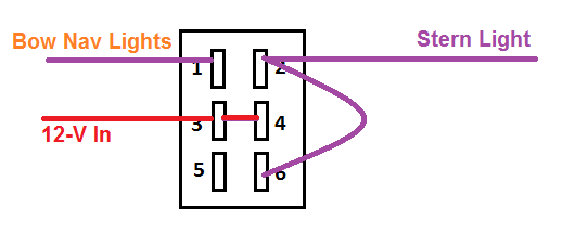 That just left the engine system, which I didn’t really have to play with too much since the wiring is internal to the outboard and the starter switch and choke were already wired into the harness. I just had to run the wires from the starter switch and choke back to the engine and plug into the harness. If you do have to work on the wiring for your engine, a shop manual with a good wiring diagram is worth its weight in gold. As I noted above, an engine this old does not follow the ABYC wiring standards and having a playbook makes things a lot simpler than having to chase wires to figure out what they do. 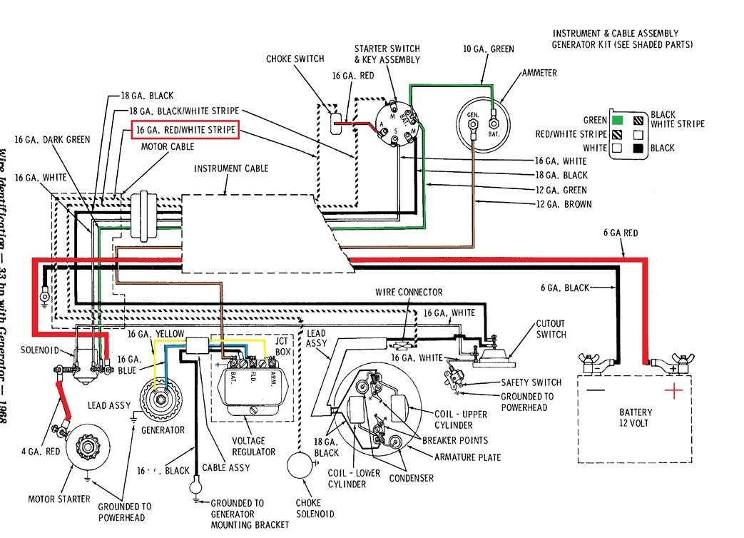 I’m thinking I may do a separate post on the outboard and marine engines in general, but for our purposes here I will detail the starter switch and choke wiring (note this will be different for newer engines). As you can hopefully see in the photo below, my starter switch and choke switch are wired as per the diagram above. The green wire supplied voltage from the engine/battery (power in); the starter switch then has four other terminals. These should be marked M, S, A, and M. I know that’s two Ms, what the heck is going on here? The S is for the starter solenoid and is a white wire on our set-up; this is powered when the key is turned to the start position (to engage the starter). The A is for accessory and is powered when the key is in the on position; if we had accessories (like a radio) that we wanted to power when the engine was on they would be run on this terminal, but in this case we only jumper from this terminal to the choke switch (red wire) which then runs back to the engine to engage the choke (red wire with white stripe). The M terminals are your kill switch; when the key is in the off position, these two terminals should be connected, which will kill your engine (black ground wire and black wire with white stripe for the kill switch). With that all connected the only thing left to do was see if the engine would fire up…but that will have to wait for another blog post. 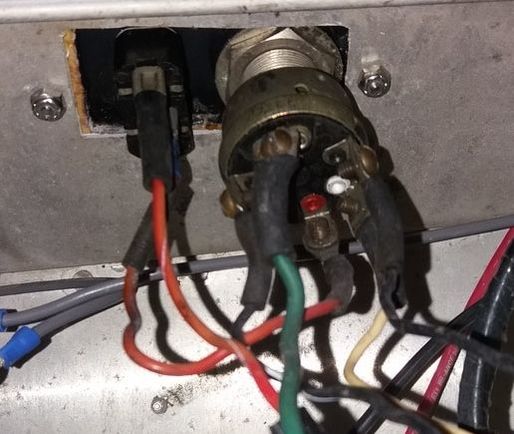 Until next time, here’s wishing you fair winds and following seas.
0 Comments
Leave a Reply. |
AuthorBrent Pounds has over a decade of experience in the maritime industry and has been involved in recreations boating since he was a child. See the About section for more detailed information. Archives
October 2016
Categories
All
|
 RSS Feed